POWER STEERING SYSTEM Drive Mode Select Switch Circuit
DESCRIPTION
The electronic throttle and the EPS character change by the operation of the drive mode select switch (electric parking brake switch assembly).
WIRING DIAGRAM
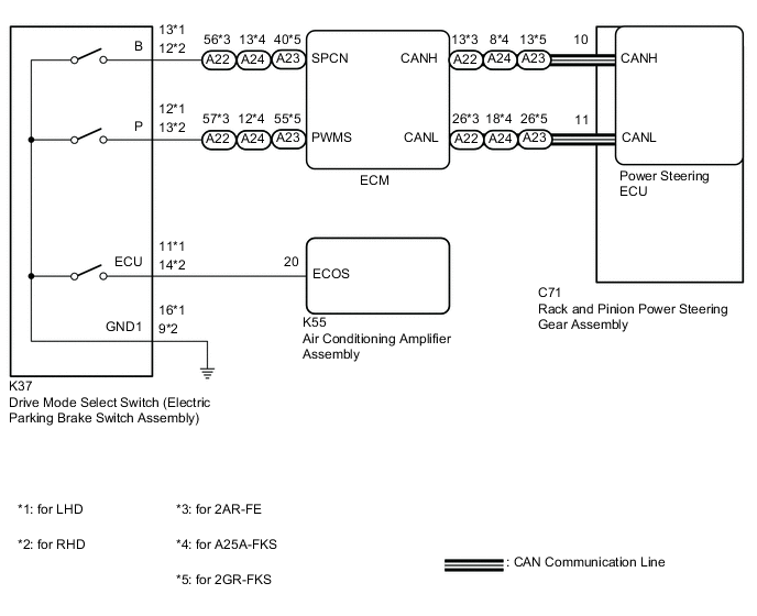
PROCEDURE
-
CHECK THE PROBLEM SYMPTOMS
-
Check each symptom by checking the suspected areas in the table below.
Result Result Proceed to SPORT mode or NORMAL mode is abnormal. A ECO mode is abnormal. B
B 
GO TO AIR CONDITIONING SYSTEM Click here
A 
-
-
CHECK CAN COMMUNICATION SYSTEM
-
Check for DTCs.
Result Result Proceed to CAN communication system DTCs are not output. A CAN communication system DTCs are output. B
B
GO TO CAN COMMUNICATION SYSTEM Click here
A
-
-
CHECK HARNESS AND CONNECTOR (DRIVE MODE SELECT SWITCH (ELECTRIC PARKING BRAKE SWITCH ASSEMBLY) - BODY GROUND)
-
Turn the ignition switch off.
-
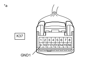
*a Front view of wire harness connector
(to Drive mode select switch (electric parking brake switch assembly))
Disconnect the K37 drive mode select switch (electric parking brake switch assembly) connector.
-
Measure the resistance according to the value(s) in the table below.
Standard Resistance Tester Connection Condition Specified Condition K37-9 (GND1) - Body ground Always Below 1 Ω Result Proceed to OK NG
NG
REPAIR OR REPLACE HARNESS OR CONNECTOR
OK
-
-
INSPECT DRIVE MODE SELECT SWITCH (ELECTRIC PARKING BRAKE SWITCH ASSEMBLY)
-
Inspect drive mode select switch (electric parking brake switch assembly).
for UA80E: Click here
for UB80E: Click here
for U760E: Click here
OK Drive mode select switch (electric parking brake switch assembly) is normal. Result Result Proceed to CAN communication system DTCs are not output. (for 2AR-FE) A CAN communication system DTCs are not output. (for A25A-FKS) B CAN communication system DTCs are not output. (for 2GR-FKS) C CAN communication system DTCs are output. D
B 
CHECK ECM (DRIVE MODE SELECT SWITCH (ELECTRIC PARKING BRAKE SWITCH ASSEMBLY) - ECM) Click here
C
CHECK ECM (DRIVE MODE SELECT SWITCH (ELECTRIC PARKING BRAKE SWITCH ASSEMBLY) - ECM) Click here
D
REPLACE DRIVE MODE SELECT SWITCH (ELECTRIC PARKING BRAKE SWITCH ASSEMBLY) for UA80E: Click here
REPLACE DRIVE MODE SELECT SWITCH (ELECTRIC PARKING BRAKE SWITCH ASSEMBLY) for UB80E: Click here
REPLACE DRIVE MODE SELECT SWITCH (ELECTRIC PARKING BRAKE SWITCH ASSEMBLY) for U760E: Click hereA
-
-
CHECK ECM (DRIVE MODE SELECT SWITCH (ELECTRIC PARKING BRAKE SWITCH ASSEMBLY) - ECM)
-
Reconnect the K37 drive mode select switch (electric parking brake switch assembly) connector.
-
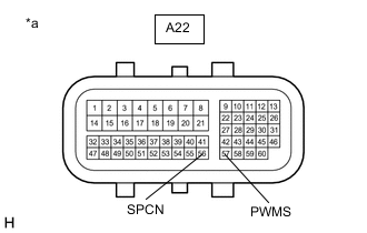
*a Front view of wire harness connector
(to ECM)
Disconnect the A22 ECM connectors.
-
Measure the resistance according to the value(s) in the table below.
Standard Resistance Tester Connection Condition Specified Condition A22-57 (PWMS) - Body ground SPORT mode switch being turned and held Below 1 Ω A22-57 (PWMS) - Body ground SPORT mode switch not turned 10 kΩ or higher A22-56 (SPCN) - Body ground NORMAL mode switch being pushed and held Below 1 Ω A22-56 (SPCN) - Body ground NORMAL mode switch not pushed 10 kΩ or higher Result Proceed to OK NG
OK
REPLACE ECM Click here
NG
REPAIR OR REPLACE HARNESS OR CONNECTOR
-
-
CHECK ECM (DRIVE MODE SELECT SWITCH (ELECTRIC PARKING BRAKE SWITCH ASSEMBLY) - ECM)
-
Reconnect the K37 drive mode select switch (electric parking brake switch assembly) connector.
-
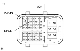
*a Front view of wire harness connector
(to ECM)
Disconnect the A24 ECM connectors.
-
Measure the resistance according to the value(s) in the table below.
Standard Resistance Tester Connection Condition Specified Condition A24-12 (PWMS) - Body ground SPORT mode switch being turned and held Below 1 Ω A24-12 (PWMS) - Body ground SPORT mode switch not turned 10 kΩ or higher A24-13 (SPCN) - Body ground NORMAL mode switch being pushed and held Below 1 Ω A24-13 (SPCN) - Body ground NORMAL mode switch not pushed 10 kΩ or higher Result Proceed to OK NG
OK
REPLACE ECM Click here
NG
REPAIR OR REPLACE HARNESS OR CONNECTOR
-
-
CHECK ECM (DRIVE MODE SELECT SWITCH (ELECTRIC PARKING BRAKE SWITCH ASSEMBLY) - ECM)
-
Reconnect the K37 drive mode select switch (electric parking brake switch assembly) connector.
-
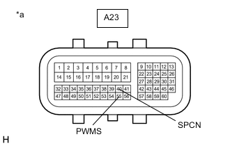
*a Front view of wire harness connector
(to ECM)
Disconnect the A23 ECM connectors.
-
Measure the resistance according to the value(s) in the table below.
Standard Resistance Tester Connection Condition Specified Condition A23-55 (PWMS) - Body ground SPORT mode switch being turned and held Below 1 Ω A23-55 (PWMS) - Body ground SPORT mode switch not turned 10 kΩ or higher A23-40 (SPCN) - Body ground NORMAL mode switch being pushed and held Below 1 Ω A23-40 (SPCN) - Body ground NORMAL mode switch not pushed 10 kΩ or higher Result Proceed to OK NG
OK
REPLACE ECM Click here
NG
REPAIR OR REPLACE HARNESS OR CONNECTOR
-