VACUUM WARNING SWITCH REMOVAL
CAUTION / NOTICE / HINT
The necessary procedures (adjustment, calibration, initialization or registration) that must be performed after parts are removed and installed, or replaced during vacuum warning switch assembly removal/installation are shown below.
| Replaced Part or Performed Procedure | Necessary Procedure | Effect/Inoperative Function when Necessary Procedure not Performed | Link |
|---|---|---|---|
| Disconnect cable from negative battery terminal*1 | Perform steering sensor zero point calibration | Lane departure alert system (w/ Steering Control) | |
| Pre-collision system | |||
| Memorize steering angle neutral point | Parking assist monitor system |
PROCEDURE
-
PRECAUTION (for LHD)
Note
After turning the ignition switch off, waiting time may be required before disconnecting the cable from the negative (-) battery terminal. Therefore, make sure to read the disconnecting the cable from the negative (-) battery terminal notices before proceeding with work.
-
REMOVE BATTERY (for LHD)
for A25A-FKS: Click here
for 2GR-FKS: Click here
-
REMOVE COWL TOP VENTILATOR LOUVER SUB-ASSEMBLY (for RHD)
-
REMOVE FRONT CENTER UPPER SUSPENSION BRACE SUB-ASSEMBLY (for RHD)
-
REMOVE VACUUM WARNING SWITCH ASSEMBLY
-
for LHD:
-
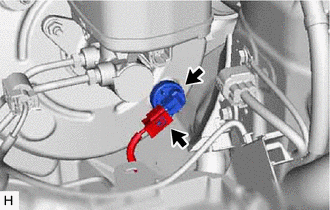
Disconnect the connector from the vacuum warning switch assembly.
-
Remove the vacuum warning switch assembly from the brake booster assembly.
-
-
for RHD:
-
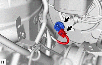
Disconnect the connector from the vacuum warning switch assembly.
-
Remove the vacuum warning switch assembly from the brake booster assembly.
-
-
-
REMOVE CHECK VALVE GROMMET
-
Remove the check valve grommet from the brake booster assembly.
-