BRAKE BOOSTER(for RHD) REMOVAL
CAUTION / NOTICE / HINT
Note
Make sure to release vacuum from the brake booster assembly before removing the brake master cylinder sub-assembly from the brake booster assembly.
PROCEDURE
-
RECOVER REFRIGERANT FROM REFRIGERATION SYSTEM
-
REMOVE ENGINE ASSEMBLY WITH TRANSAXLE (for 2GR-FKS)
-
REMOVE BRAKE MASTER CYLINDER SUB-ASSEMBLY
-
REMOVE FRONT DOOR SCUFF PLATE RH
-
REMOVE COWL SIDE TRIM SUB-ASSEMBLY RH
-
REMOVE NO. 1 INSTRUMENT PANEL UNDER COVER SUB-ASSEMBLY
-
SEPARATE SUCTION PIPE SUB-ASSEMBLY
-
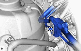
Disengage the clamp to separate the suction pipe sub-assembly from the brake tube clamp bracket.
Note
-
Do not deform the refrigerant lines.
-
Do not damage the clamp.
-
-
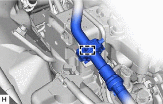
Disengage the clamp to separate the suction pipe sub-assembly from the engine mounting insulator sub-assembly RH.
Note
-
Do not deform the refrigerant lines.
-
Do not damage the clamp.
-
-
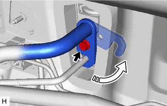
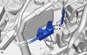
Remove the bolt and rotate the hook connector as shown in the illustration.
-
Disconnect the suction pipe sub-assembly from the air conditioning unit assembly.
-
Remove the O-ring from the suction pipe sub-assembly.
Note
Seal the openings of the disconnected parts using vinyl tape to prevent entry of moisture and foreign matter.
-
-
SEPARATE AIR CONDITIONER TUBE AND ACCESSORY ASSEMBLY
-
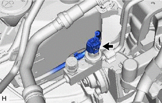
Disconnect the connector from the air conditioner tube and accessory assembly.
-
Disengage the clamp to separate the air conditioner tube and accessory assembly.
Note
-
Do not deform the refrigerant lines.
-
Do not damage the clamp.
-
-
Disconnect the air conditioner tube and accessory assembly from the air conditioning unit assembly.
-
Remove the O-ring from the air conditioner tube and accessory assembly.
Note
Seal the openings of the disconnected parts using vinyl tape to prevent entry of moisture and foreign matter.
-
-
DISCONNECT UNION TO CHECK VALVE HOSE
-
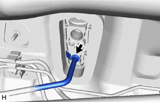
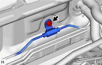
Slide the clip and disconnect the union to check valve hose from the brake booster assembly.
-
-
LOOSEN LOCK NUT
-
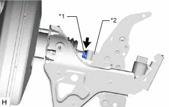
*1 Lock Nut *2 Brake Master Cylinder Push Rod Clevis Loosen the lock nut of the brake master cylinder push rod clevis.
-
-
REMOVE PUSH ROD PIN
-
SEPARATE BRAKE LINE
-
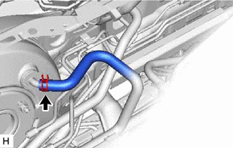
Remove the bolt and separate the front brake tube way from the vehicle body.
-
Disengage the clamp and separate the No. 2 brake tube clamp from the vehicle body.
Note
Do not kink or damage the brake lines.
-
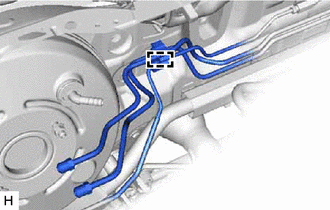
Disengage the 3 clamps to remove the No. 2 brake tube clamp from the brake lines.
Note
Do not kink or damage the brake lines.
-
-
REMOVE BRAKE BOOSTER ASSEMBLY
-
for 2GR-FKS:
-
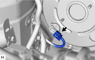
Disconnect the connector from the vacuum warning switch assembly.
-
-
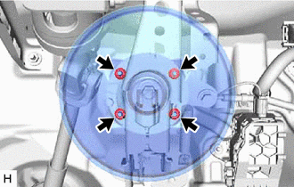
Remove the 4 nuts and push the brake booster assembly toward the engine compartment.
Note
Do not apply excessive force to the brake lines or refrigerant lines.
-
Remove the brake master cylinder push rod clevis and lock nut from the brake booster assembly.
-
Remove the brake booster assembly from the vehicle body.
Note
Do not apply excessive force to the brake lines or refrigerant lines.
-
-
REMOVE BRAKE BOOSTER GASKET