BRAKE BOOSTER(for LHD) REMOVAL
CAUTION / NOTICE / HINT
The necessary procedures (adjustment, calibration, initialization or registration) that must be performed after parts are removed and installed, or replaced during brake booster assembly removal/installation are shown below.
| Replaced Part or Performed Procedure | Necessary Procedure | Effect/Inoperative Function when Necessary Procedure not Performed | Link |
|---|---|---|---|
| Disconnect cable from negative battery terminal | Perform steering sensor zero point calibration | Lane departure alert system (w/ Steering Control) | |
| Pre-collision system | |||
| Memorize steering angle neutral point | Parking assist monitor system |
CAUTION / NOTICE / HINT
Note
Make sure to release vacuum from the brake booster assembly before removing the brake master cylinder sub-assembly from the brake booster assembly.
PROCEDURE
-
PRECAUTION
Note
After turning the ignition switch off, waiting time may be required before disconnecting the cable from the negative (-) battery terminal. Therefore, make sure to read the disconnecting the cable from the negative (-) battery terminal notices before proceeding with work.
-
REMOVE BRAKE MASTER CYLINDER SUB-ASSEMBLY
-
REMOVE NO. 1 INSTRUMENT PANEL UNDER COVER SUB-ASSEMBLY
-
REMOVE COWL TOP VENTILATOR LOUVER SUB-ASSEMBLY
-
REMOVE FRONT CENTER UPPER SUSPENSION BRACE SUB-ASSEMBLY
-
REMOVE AIR CLEANER ASSEMBLY WITH AIR CLEANER HOSE (for 2AR-FE)
-
REMOVE NO. 1 ENGINE COVER SUB-ASSEMBLY (for A25A-FKS)
-
REMOVE AIR CLEANER ASSEMBLY WITH AIR CLEANER HOSE (for A25A-FKS)
-
REMOVE AIR CLEANER ASSEMBLY WITH AIR CLEANER HOSE (for 2GR-FKS)
-
REMOVE BATTERY CLAMP SUB-ASSEMBLY
-
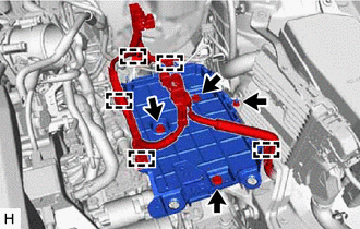
for A25A-FKS:
-
Disengage the 4 clamps from the battery clamp sub-assembly.
-
Remove the 3 bolts, nut and battery clamp sub-assembly.
-
-
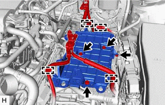
for 2AR-FE, 2GR-FKS:
-
Disengage the 5 clamps from the battery clamp sub-assembly.
-
Remove the 3 bolts, nut and battery clamp sub-assembly.
-
-
-
DISCONNECT UNION TO CHECK VALVE HOSE (for A25A-FKS, 2GR-FKS)
-
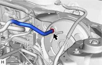
Slide the clip and disconnect the union to check valve hose from the brake booster assembly.
-
-
SEPARATE NO. 1 HOSE TO HOSE TUBE (for 2AR-FE)
-
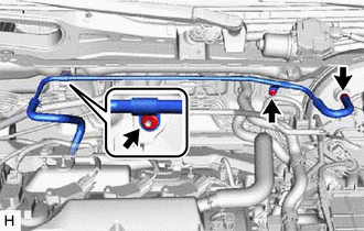
Slide the clip and disconnect the check valve to connector tube hose from the brake booster assembly.
-
Remove the 2 nuts and separate the No. 1 hose to hose tube from the vehicle body.
-
-
LOOSEN LOCK NUT
-
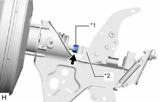
*1 Lock Nut *2 Brake Master Cylinder Push Rod Clevis Loosen the lock nut of the brake master cylinder push rod clevis.
-
-
REMOVE PUSH ROD PIN
-
REMOVE BRAKE BOOSTER ASSEMBLY
-
for A25A-FKS, 2GR-FKS:
-
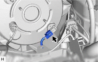
Disconnect the connector from the vacuum warning switch assembly.
-
-
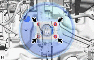
Remove the 4 nuts and push the brake booster assembly toward the engine compartment.
Note
Do not apply excessive force to the brake lines.
-
Remove the brake master cylinder push rod clevis and lock nut from the brake booster assembly.
-
Remove the brake booster assembly from the vehicle body.
Note
Do not apply excessive force to the brake lines.
-
-
REMOVE BRAKE BOOSTER GASKET