BRAKE PEDAL(for RHD) INSTALLATION
PROCEDURE
-
INSTALL BRAKE PEDAL PAD
-
Install the brake pedal pad to the brake pedal support assembly.
-
-
INSTALL STOP LIGHT SWITCH MOUNTING ADJUSTER
-
Engage the 2 claws to install the stop light switch mounting adjuster.
-
-
INSTALL BRAKE PEDAL RETURN SPRING
-
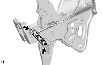
Install the brake pedal return spring to the brake pedal support assembly.
Note
Attach the bottom part of the brake pedal return spring first, making sure that the open part of the hook is facing the front of the vehicle. Attach the top part of the brake pedal return spring second, making sure that the open part of the hook is facing the rear of the vehicle.
-
-
INSTALL BRAKE PEDAL SUPPORT ASSEMBLY
-
Push the brake booster assembly toward the engine compartment, and install the brake pedal support assembly while avoiding the stud bolts of the brake booster assembly and brake booster support base.
Note
-
Be careful not to deform the bracket of the instrument panel reinforcement assembly.
-
Do not apply excessive force to the brake lines.
-
Do not apply excessive force to the wire harness.
-
-
Return the brake booster assembly to its original position.
-
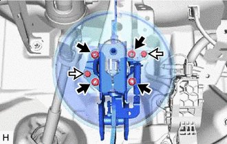

Nut 
Clip Temporarily install the brake pedal support assembly with 2 new clips.
-
Install the 4 nuts.
- Torque:
- 12.8 N*m { 131 kgf*cm, 9 ft.*lbf }
-
Install the brake pedal support assembly to the instrument panel reinforcement assembly with the bolt.
- Torque:
- 15 N*m { 153 kgf*cm, 11 ft.*lbf }
-
Engage the clamp to install the wire harness to the brake pedal support assembly.
-
-
INSTALL PUSH ROD PIN
-
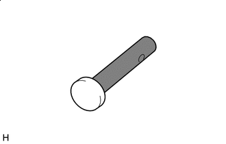

Lithium Soap Base Glycol Grease Apply lithium soap base glycol grease to the push rod pin.
-
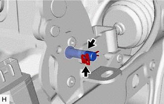
Connect the brake master cylinder push rod clevis to the brake pedal support assembly with the push rod pin, and install a new clip as shown in the illustration.
Tech Tips
The push rod pin can be installed in either direction.
-
-
INSTALL STOP LIGHT SWITCH ASSEMBLY
-
INSTALL NO. 1 INSTRUMENT PANEL UNDER COVER SUB-ASSEMBLY
-
INSTALL COWL SIDE TRIM SUB-ASSEMBLY RH
-
INSTALL FRONT DOOR SCUFF PLATE RH
-
CONNECT BRAKE LINE
-
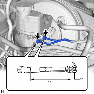
*a Torque Wrench Fulcrum Length *b Union Nut Wrench Using a union nut wrench, connect the 2 brake lines to the brake master cylinder sub-assembly.
- Torque:
- Specified tightening torque
- 19.5 N*m { 199 kgf*cm, 14 ft.*lbf }
Note
-
Do not kink or damage the brake lines.
-
Do not allow the brake lines to twist or interfere with other parts or the vehicle body during tightening.
-
Do not allow any foreign matter such as dirt or dust to enter the brake lines from the connecting parts.
Tech Tips
-
Calculate the torque wrench reading when changing the fulcrum length of the torque wrench.
-
When using a union nut wrench (fulcrum length of 20 mm (0.787 in.)) + torque wrench (fulcrum length of 162 mm (6.38 in.)):
17.4 N*m (177 kgf*cm, 13 ft.*lbf)
-
Connect the connector to the brake master cylinder sub-assembly.
-
Install the wire harness to the brake master cylinder sub-assembly.
-
-
BLEED BRAKE SYSTEM
-
INSTALL FRONT CENTER UPPER SUSPENSION BRACE SUB-ASSEMBLY
-
INSTALL COWL TOP VENTILATOR LOUVER SUB-ASSEMBLY
-
INSPECT AND ADJUST BRAKE PEDAL