BRAKE PEDAL(for RHD) REMOVAL
PROCEDURE
-
REMOVE COWL TOP VENTILATOR LOUVER SUB-ASSEMBLY
-
REMOVE FRONT CENTER UPPER SUSPENSION BRACE SUB-ASSEMBLY
-
DRAIN BRAKE FLUID
Note
If brake fluid leaks onto any painted surface, immediately wash it off.
-
DISCONNECT BRAKE LINE
-
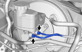
Disconnect the connector from the brake master cylinder sub-assembly.
-
Separate the wire harness from the brake master cylinder sub-assembly.
-
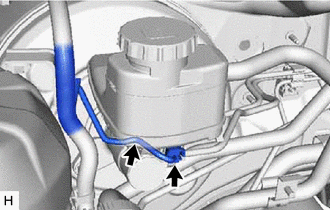
Using a union nut wrench, disconnect the 2 brake lines from the brake master cylinder sub-assembly.
Note
-
Do not damage or deform the brake lines.
-
Do not allow any foreign matter such as dirt or dust to enter the brake lines from the connecting parts.
-
-
-
REMOVE FRONT DOOR SCUFF PLATE RH
-
REMOVE COWL SIDE TRIM SUB-ASSEMBLY RH
-
REMOVE NO. 1 INSTRUMENT PANEL UNDER COVER SUB-ASSEMBLY
-
REMOVE STOP LIGHT SWITCH ASSEMBLY
-
REMOVE PUSH ROD PIN
-
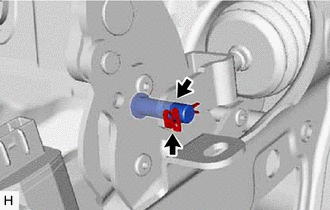
Remove the clip and push rod pin.
-
-
REMOVE BRAKE PEDAL SUPPORT ASSEMBLY
-
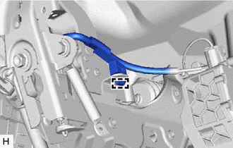
Disengage the clamp to separate the wire harness from the brake pedal support assembly.
-
Remove the bolt and separate the brake pedal support assembly from the instrument panel reinforcement assembly.
-

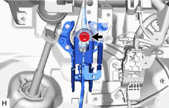
Nut 
Clip Remove the 2 clips.
-
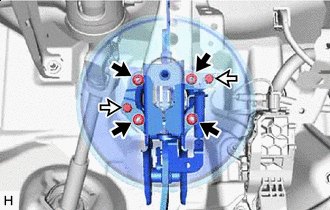
Remove the 4 nuts and push the brake booster assembly toward the engine compartment.
Note
-
Do not apply excessive force to the brake lines.
-
Do not apply excessive force to the wire harness.
-
-
Remove the brake pedal support assembly while avoiding the stud bolts of the brake booster assembly and brake booster support base.
Note
Be careful not to deform the bracket of the instrument panel reinforcement assembly.
-
-
REMOVE BRAKE PEDAL RETURN SPRING
-
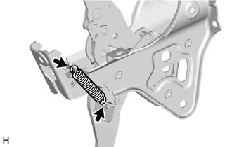
Remove the brake pedal return spring from the brake pedal support assembly.
-
-
REMOVE STOP LIGHT SWITCH MOUNTING ADJUSTER
-
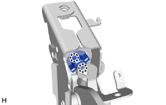
Disengage the 2 claws and remove the stop light switch mounting adjuster.
-
-
REMOVE BRAKE PEDAL PAD
-
Remove the brake pedal pad from the brake pedal support assembly.
-