CAUTION / NOTICE / HINT
The necessary procedures (adjustment, calibration, initialization or registration) that must be performed after parts are removed and installed, or replaced during brake pedal support assembly removal/installation are shown below.
| Replaced Part or Performed Procedure | Necessary Procedure | Effect/Inoperative Function when Necessary Procedure not Performed | Link |
|---|---|---|---|
| Disconnect cable from negative battery terminal | Perform steering sensor zero point calibration | Lane departure alert system (w/ Steering Control) | |
| Pre-collision system | |||
| Memorize steering angle neutral point | Parking assist monitor system |
PROCEDURE
- Click here
PRECAUTION
Note:After turning the ignition switch off, waiting time may be required before disconnecting the cable from the negative (-) battery terminal. Therefore, make sure to read the disconnecting the cable from the negative (-) battery terminal notices before proceeding with work.
- Click here
REMOVE BATTERY
for 2AR-FE:Click here
for A25A-FKS:Click here
for 2GR-FKS:Click here
- Click here
DRAIN BRAKE FLUID
Note:If brake fluid leaks onto any painted surface, immediately wash it off.
- Click here
DISCONNECT BRAKE LINE
-
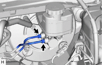
Using a union nut wrench, disconnect the 2 brake lines from the brake master cylinder sub-assembly.
Note:
-
Do not damage or deform the brake lines.
-
Do not allow any foreign matter such as dirt or dust to enter the brake lines from the connecting parts.
-
-
- Click here
REMOVE NO. 1 INSTRUMENT PANEL UNDER COVER SUB-ASSEMBLY
- Click here
REMOVE STOP LIGHT SWITCH ASSEMBLY
- Click here
REMOVE PUSH ROD PIN
-
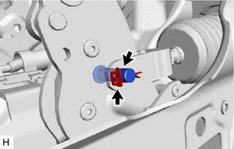
Remove the clip and push rod pin.
-
- Click here
REMOVE BRAKE PEDAL SUPPORT ASSEMBLY
-
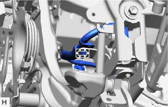
Disengage the clamp to separate the wire harness from the brake pedal support assembly.
-
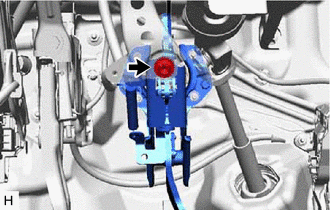
Remove the bolt and separate the brake pedal support assembly from the instrument panel reinforcement assembly.
-
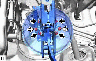

Nut 
Clip Remove the 2 clips.
-
Remove the 4 nuts and push the brake booster assembly toward the engine compartment.
Note:
-
Do not apply excessive force to the brake lines.
-
Do not apply excessive force to the wire harness.
-
-
Remove the brake pedal support assembly while avoiding the stud bolts of the brake booster assembly and brake booster support base.
Note:Be careful not to deform the bracket of the instrument panel reinforcement assembly.
-
- Click here
REMOVE BRAKE PEDAL RETURN SPRING
-
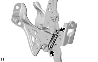
Remove the brake pedal return spring from the brake pedal support assembly.
-
- Click here
REMOVE STOP LIGHT SWITCH MOUNTING ADJUSTER
-
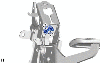
Disengage the 2 claws and remove the stop light switch mounting adjuster.
-
- Click here
REMOVE BRAKE PEDAL PAD
-
Remove the brake pedal pad from the brake pedal support assembly.
-