BRAKE BOOSTER(for RHD) INSTALLATION
PROCEDURE
-
INSTALL BRAKE BOOSTER GASKET
-
Install a new brake booster gasket to the brake booster assembly.
-
-
INSTALL BRAKE BOOSTER ASSEMBLY
-
Temporarily install the brake booster assembly to the vehicle body.
Note
Do not apply excessive force to the brake lines or refrigerant lines.
-
Temporarily install the lock nut and brake master cylinder push rod clevis to the brake booster assembly.
Note
Fully tighten the lock nut when adjusting the brake pedal height.
-
Install the 4 nuts to secure the brake booster assembly.
- Torque:
- 12.8 N*m { 131 kgf*cm, 9 ft.*lbf }
-
-
INSTALL PUSH ROD PIN
-
INSTALL BRAKE LINE
-
Engage the 3 clamps to install a new No. 2 brake tube clamp to the brake lines.
Note
Do not kink or damage the brake lines.
-
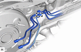
Engage the clamp and install the No. 2 brake tube clamp to the vehicle body.
Note
Do not kink or damage the brake lines.
-
Install the front brake tube way to the vehicle body with the bolt.
- Torque:
- 7.0 N*m { 71 kgf*cm, 62 in.*lbf }
-
-
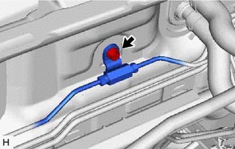
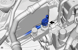
CONNECT UNION TO CHECK VALVE HOSE
-
Connect the union to check valve hose to the brake booster assembly and slide the clip to secure it.
-
-
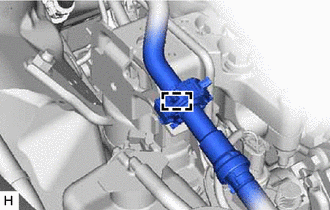
CONNECT AIR CONDITIONER TUBE AND ACCESSORY ASSEMBLY
-
Remove the vinyl tape from the air conditioner tube and accessory assembly.
-
Sufficiently apply compressor oil to a new O-ring and the fitting surface of the air conditioner tube and accessory assembly.
Compressor Oil ND-OIL 8 or equivalent -
Install the O-ring to the air conditioner tube and accessory assembly.
Note
Keep the O-ring and O-ring fitting surface free of foreign matter.
-
Insert the air conditioner tube and accessory assembly to the air conditioning unit assembly.
-
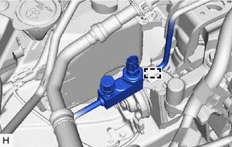
Engage the clamp to install the air conditioner tube and accessory assembly.
Note
-
Do not deform the refrigerant lines.
-
Do not damage the clamp.
-
-
Connect the connector to the air conditioner tube and accessory assembly.
-
-
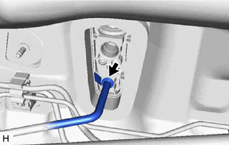
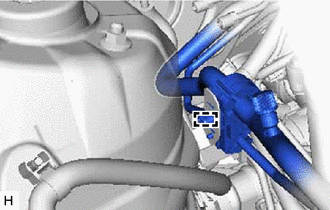
CONNECT SUCTION PIPE SUB-ASSEMBLY
-
Remove the vinyl tape from the suction pipe sub-assembly.
-
Sufficiently apply compressor oil to a new O-ring and the fitting surface of the suction pipe sub-assembly.
Compressor Oil ND-OIL 8 or equivalent -
Install the O-ring to the suction pipe sub-assembly.
Note
Keep the O-ring and O-ring fitting surface free of foreign matter.
-
Insert the suction pipe sub-assembly to the air conditioning unit assembly.
-
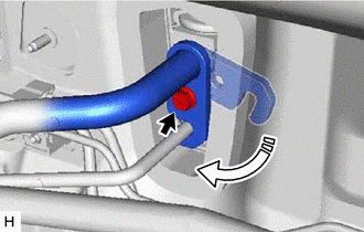
Rotate the hook connector as shown in the illustration.
-
Insert the tube joint into the fitting hole securely and install the bolt.
- Torque:
- 9.8 N*m { 100 kgf*cm, 87 in.*lbf }
-
Engage the clamp to install the suction pipe sub-assembly to the engine mounting insulator sub-assembly RH.
Note
-
Do not deform the refrigerant lines.
-
Do not damage the clamp.
-
-
Engage the clamp to install the suction pipe sub-assembly to the brake tube clamp bracket.
Note
-
Do not deform the refrigerant lines.
-
Do not damage the clamp.
-
-
-
INSTALL NO. 1 INSTRUMENT PANEL UNDER COVER SUB-ASSEMBLY
-
INSTALL COWL SIDE TRIM SUB-ASSEMBLY RH
-
INSTALL FRONT DOOR SCUFF PLATE RH
-
INSTALL BRAKE MASTER CYLINDER SUB-ASSEMBLY
-
CHARGE AIR CONDITIONING SYSTEM WITH REFRIGERANT
-
WARM UP ENGINE
-
INSPECT FOR REFRIGERANT LEAK
-
INSPECT AND ADJUST BRAKE PEDAL