CAUTION / NOTICE / HINT
The necessary procedures (adjustment, calibration, initialization or registration) that must be performed after parts are removed and installed, or replaced during brake actuator assembly removal/installation are shown below.
| Replaced Part or Performed Procedure | Necessary Procedure | Effect/Inoperative Function when Necessary Procedure not Performed | Link |
|---|---|---|---|
| Disconnect cable from negative battery terminal | Perform steering sensor zero point calibration | Lane departure alert system (w/ Steering Control) | |
| Pre-collision system | |||
| Memorize steering angle neutral point | Parking assist monitor system | ||
| Replacement of brake actuator assembly | Operate the electric parking brake switch (electric parking brake switch assembly) | Parking brake indicator light (red) blinks when the ignition switch is first turned on (IG) | |
| Perform system variant learning and acceleration sensor zero point calibration. |
|
PROCEDURE
- Click here
PRECAUTION
Note:After turning the ignition switch off, waiting time may be required before disconnecting the cable from the negative (-) battery terminal. Therefore, make sure to read the disconnecting the cable from the negative (-) battery terminal notices before proceeding with work.
- Click here
REMOVE BATTERY
for 2AR-FE:Click here
for 2GR-FKS:Click here
- Click here
DRAIN BRAKE FLUID
Note:If brake fluid leaks onto any painted surface, immediately wash it off.
- Click here
REMOVE FRONT WHEEL LH
- Click here
REMOVE COWL TOP VENTILATOR LOUVER SUB-ASSEMBLY
- Click here
REMOVE FRONT CENTER UPPER SUSPENSION BRACE SUB-ASSEMBLY
-
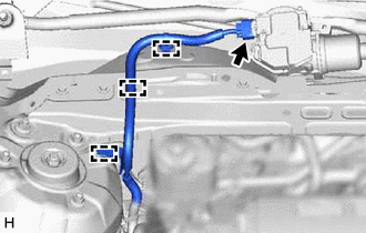
Disconnect the connector.
-
Disengage the 3 clamps and separate the wire harness.
-
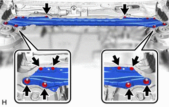
Remove the 6 bolts, 4 nuts and front center upper suspension brace sub-assembly.
-
- Click here
REMOVE AIR CLEANER ASSEMBLY WITH AIR CLEANER HOSE (for 2AR-FE)
- Click here
REMOVE AIR CLEANER ASSEMBLY WITH AIR CLEANER HOSE (for 2GR-FKS)
- Click here
REMOVE BATTERY CLAMP SUB-ASSEMBLY
-
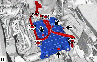
Disengage the 5 clamps from the battery clamp sub-assembly.
-
Remove the 3 bolts, nut and battery clamp sub-assembly.
-
- Click here
REMOVE BRAKE ACTUATOR WITH BRACKET
-
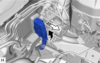

Release the lock lever 
Disconnect the connector Release the lock lever and disconnect the connector from the brake actuator assembly.
Note:Be careful not to allow any brake fluid to enter the connector.
-
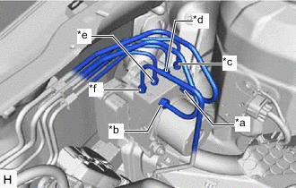
*a From 1st Chamber of Brake Master Cylinder Sub-assembly *b From 2nd Chamber of Brake Master Cylinder Sub-assembly *c To Front Wheel Cylinder Assembly RH *d To Rear Wheel Cylinder Assembly LH *e To Rear Wheel Cylinder Assembly RH *f To Front Wheel Cylinder Assembly LH Use tags or make a memo to identify the places to reconnect the brake lines.
-
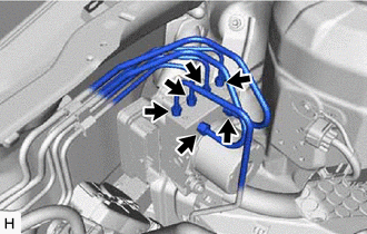
Using a union nut wrench, disconnect the 6 brake lines from the brake actuator assembly.
Note:
-
Do not kink or damage the brake lines.
-
Do not allow any foreign matter such as dirt or dust to enter the brake lines from the connecting parts.
-
-
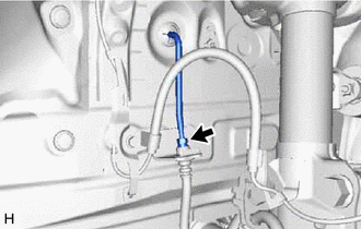
Using a union nut wrench, disconnect the front No. 5 brake tube while holding the front flexible hose with a wrench.
Note:
-
Do not kink or damage the front No. 5 brake tube.
-
Do not allow any foreign matter such as dirt or dust to enter the front No. 5 brake tube from the connecting parts.
-
-
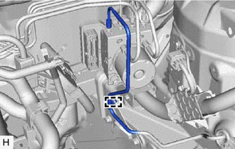
Disengage the clamp and separate the front No. 5 brake tube.
Note:Do not kink or damage the front No. 5 brake tube.
-
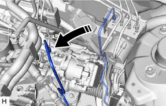
Move aside the front No. 5 brake tube as shown in the illustration.
Note:Do not apply excessive force to the front No. 5 brake tube.
-
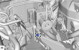
Disengage the clamp and remove the brake tube clamp.
-
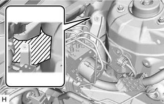

Protective Tape Apply protective tape to the vehicle body as shown in the illustration.
-
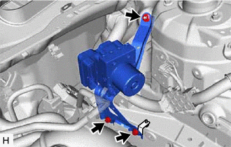
Remove the 2 bolts, nut and brake actuator with bracket.
Note:
-
Do not kink or damage the brake lines.
-
Do not allow any foreign matter such as dirt or dust to enter the brake lines from the connecting parts.
-
Be careful not to allow any brake fluid to enter the connector.
-
Do not hold the brake actuator assembly by the connector.
-
Do not drop the brake actuator with bracket when carrying it.
Tip:Remove the brake actuator with bracket while avoiding the brake lines.
-
-
- Click here
REMOVE BRAKE ACTUATOR ASSEMBLY
-
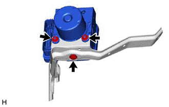
Loosen the 2 nuts.
-
Remove the bolt and brake actuator assembly from the brake actuator bracket assembly.
Note:
-
Do not hold the brake actuator assembly by the connector.
-
Do not drop the brake actuator assembly when carrying it.
-
-
- Click here
REMOVE NO. 2 BRAKE ACTUATOR CASE COLLAR
-
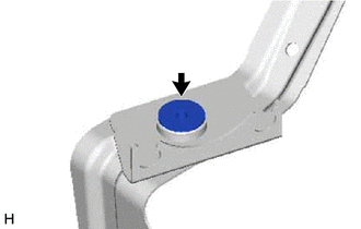
Remove the No. 2 brake actuator case collar from the brake actuator bolt cushion.
-
- Click here
REMOVE BRAKE ACTUATOR BOLT CUSHION
-
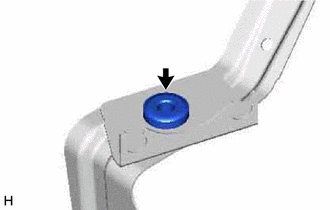
Remove the brake actuator bolt cushion from the brake actuator bracket assembly.
-