VEHICLE STABILITY CONTROL SYSTEM Slip Indicator Light Remains ON
DESCRIPTION
The skid control ECU (brake actuator assembly) is connected to the combination meter assembly via CAN communication.
The slip indicator light blinks during VSC and/or TRC operation.
If a malfunction is detected, the slip indicator light comes on to warn the driver.
WIRING DIAGRAM
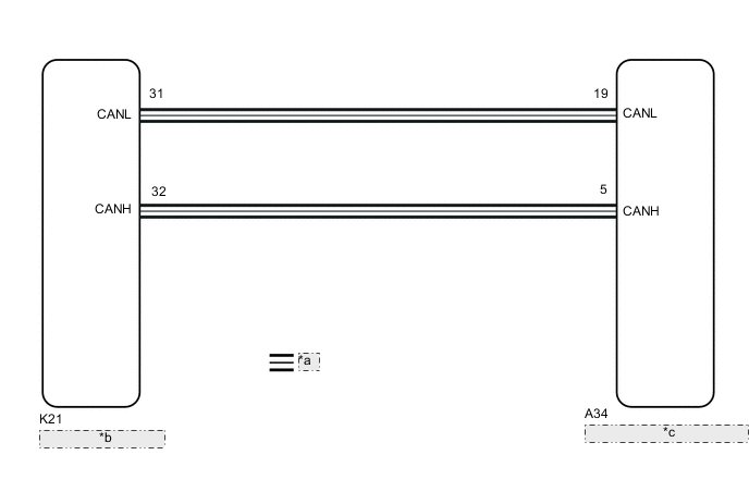
| *a | CAN Communication Line |
| *b | Combination Meter Assembly |
| *c | Skid Control ECU (Brake Actuator Assembly) |
CAUTION / NOTICE / HINT
Note
When replacing the skid control ECU (brake actuator assembly), perform system variant learning and acceleration sensor zero point calibration.
PROCEDURE
-
CHECK CAN COMMUNICATION SYSTEM
-
Check if CAN communication system DTCs are output.
Result Result Proceed to DTCs are not output A DTCs are output B
B 
INSPECT CAN COMMUNICATION SYSTEM Click here
A 
-
-
CHECK IF BRAKE ACTUATOR ASSEMBLY CONNECTOR IS SECURELY CONNECTED
-
Check if the skid control ECU (brake actuator assembly) connector is securely connected.
OK The connector is securely connected. Result Proceed to OK NG
NG
CONNECT CONNECTOR TO BRAKE ACTUATOR ASSEMBLY CORRECTLY
OK
-
-
CHECK BATTERY
-
Check the battery voltage.
Standard Voltage Tester Connection Condition Specified Condition Positive (+) terminal - Negative (-) terminal Ignition switch off 11 to 14 V Result Proceed to OK NG
NG
CHECK OR REPLACE CHARGING SYSTEM COMPONENT OR BATTERY for 2AR-FE: Click here
CHECK OR REPLACE CHARGING SYSTEM COMPONENT OR BATTERY for A25A-FKS: Click here
CHECK OR REPLACE CHARGING SYSTEM COMPONENT OR BATTERY for 2GR-FKS: Click hereOK
-
-
READ VALUE USING GTS (SLIP INDICATOR LIGHT)
-
Connect the GTS to the DLC3.
-
Turn the ignition switch to ON.
-
Enter the following menus: Chassis / ABS/VSC/TRC / Data List.
Chassis > ABS/VSC/TRC > Data ListTester Display Measurement Item Range Normal Condition Diagnostic Note Slip Indicator Light Slip indicator light ON or OFF ON: Indicator light on
OFF: Indicator light off
-
Chassis > ABS/VSC/TRC > Data ListTester Display Slip Indicator Light -
Check the GTS display condition of the slip indicator light.
Result Result Proceed to The value of Slip Indicator Light is ON A The value of Slip Indicator Light is OFF B
A
REPLACE BRAKE ACTUATOR ASSEMBLY for LHD: Click here
REPLACE BRAKE ACTUATOR ASSEMBLY for RHD: Click hereB
INSPECT METER / GAUGE SYSTEM Click here
-