VEHICLE STABILITY CONTROL SYSTEM, Diagnostic DTC:C146E
| DTC Code | DTC Name |
|---|---|
| C146E | Open in ABS Solenoid Relay Circuit |
DESCRIPTION
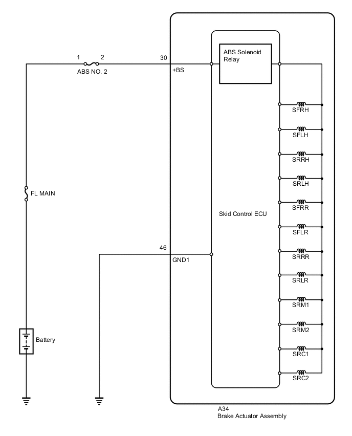
The ABS solenoid relay is built into the skid control ECU in the brake actuator assembly. The ABS solenoid relay supplies power to the ABS and TRC solenoids. The skid control ECU (brake actuator assembly) detects an ABS solenoid relay malfunction by performing a self check and relay operation check.
| DTC No. | Detection Item | DTC Detection Condition | Trouble Area |
|---|---|---|---|
| C146E | Open in ABS Solenoid Relay Circuit | Either of the following is detected:
|
|
| Vehicle Condition | |||
|---|---|---|---|
| Pattern 1 | Pattern 2 | ||
| Diagnosis Condition | - | - | - |
| Malfunction Status | The ABS solenoid relay drive circuit in the skid control ECU (brake actuator assembly) is malfunctioning. | ○ | - |
| The ABS solenoid relay cannot be switched between on and off. | - | ○ | |
| Detection Time | - | - | |
| Number of Trips | 1 trip | 1 trip | |
Tech Tips
DTC will be output when conditions for either of the patterns in the table above are met.
WIRING DIAGRAM
CAUTION / NOTICE / HINT
Note
-
When replacing the skid control ECU (brake actuator assembly), perform system variant learning and acceleration sensor zero point calibration.
-
Inspect the fuses for circuits related to this system before performing the following procedure.
PROCEDURE
-
REPLACE BRAKE ACTUATOR ASSEMBLY
-
Replace the skid control ECU (brake actuator assembly).
for LHD: Click here
for RHD: Click here
Tech Tips
This DTC is output when the skid control ECU (brake actuator assembly) detects a malfunction in an internal circuit.
-
Enter the following menus: Chassis / ABS/VSC/TRC / Utility / Test Mode.
-
Perform system variant learning and acceleration sensor zero point calibration.
Chassis > ABS/VSC/TRC > UtilityTester Display Test Mode -
Enter the following menus: Chassis / ABS/VSC/TRC / Utility / Signal Check.
-
Perform the sensor check using the Test Mode (Signal Check) procedure.
Chassis > ABS/VSC/TRC > UtilityTester Display Signal Check Result Proceed to NEXT
NEXT 
END
-