VEHICLE STABILITY CONTROL SYSTEM, Diagnostic DTC:C1426
| DTC Code | DTC Name |
|---|---|
| C1426 | Stop Light Switch OFF Stuck Malfunction |
DESCRIPTION
The skid control ECU (brake actuator assembly) receives stop light switch assembly signals and uses them to determine whether or not the brakes are applied.
The skid control ECU (brake actuator assembly) has a detection circuit that it uses to detect a short in the stop light input signal circuit or stop light circuit when the stop light switch assembly is on (brake pedal depressed).
If the skid control ECU (brake actuator assembly) detects a short in this circuit, it will store this DTC.
| DTC No. | Detection Item | DTC Detection Condition | Trouble Area |
|---|---|---|---|
| C1426 | Stop Light Switch OFF Stuck Malfunction | Either of the following is detected when the vehicle speed of 3 km/h (2 mph) or more:
|
|
| Vehicle Condition | |||
|---|---|---|---|
| Pattern 1 | Pattern 2 | ||
| Diagnosis Condition | The vehicle speed of 3 km/h (2 mph) or more. | ○ | ○ |
| The stop light switch assembly is off. | ○ | ○ | |
| Malfunction Status | The stop light switch assembly is judged to be on based on the master cylinder pressure value. | ○ | - |
| The master cylinder pressure is more than 8 MPa (81.6 kgf/cm2, 1160 psi). |
- | ○ | |
| Detection Time | 3 seconds or more | 3 seconds or more | |
| Number of Trips | 1 trip | 1 trip | |
Tech Tips
DTC will be output when conditions for either of the patterns in the table above are met.
CAUTION / NOTICE / HINT
Note
-
When replacing the skid control ECU (brake actuator assembly), perform system variant learning and acceleration sensor zero point calibration.
-
Inspect the fuses for circuits related to this system before performing the following procedure.
PROCEDURE
-
READ VALUE USING GTS (BS1 VOLTAGE VALUE)
-
Connect the GTS to the DLC3.
-
Turn the ignition switch to ON.
-
Enter the following menus: Chassis / ABS/VSC/TRC / Data List.
Chassis > ABS/VSC/TRC > Data ListTester Display Measurement Item Range Normal Condition Diagnostic Note BS1 Voltage Value +BS voltage value Min.: 0.00 V, Max.: 20.00 V - Changes in proportion to battery voltage
Chassis > ABS/VSC/TRC > Data ListTester Display BS1 Voltage Value -
Take a note of the +BS voltage value.
Tech Tips
The noted +BS voltage value is used in a later step.
Result Proceed to NEXT
NEXT 
-
-
CHECK BRAKE PEDAL AND STOP LIGHT SWITCH ASSEMBLY INSTALLATION
-
Check the brake pedal height installation.
for LHD: Click here
for RHD: Click here
-
Check the stop light switch assembly installation.
OK The brake pedal height and stop light switch assembly installation are normal. Tech Tips
If the on/off status of the stop light switch assembly and pressure increase information from the master cylinder pressure sensor do not match due to an improperly installed brake pedal or stop light switch assembly, this DTC may be stored. Therefore, be sure to check the installation condition of the pedal and switch before inspecting the input signals and other related parts.
Result Proceed to OK NG
NG 
ADJUST BRAKE PEDAL OR STOP LIGHT SWITCH ASSEMBLY for LHD: Click here
ADJUST BRAKE PEDAL OR STOP LIGHT SWITCH ASSEMBLY for RHD: Click hereOK
-
-
CHECK STOP LIGHT OPERATION
-
Check that the stop lights come on when the brake pedal is depressed, and go off when the brake pedal is released.
OK Condition Illumination Condition Brake pedal depressed On Brake pedal released Off Result Proceed to OK NG
NG 
INSPECT STOP LIGHT SWITCH ASSEMBLY Click here
OK
-
-
INSPECT STOP LIGHT SWITCH ASSEMBLY
-
Inspect the stop light switch assembly.
OK The stop light switch assembly is normal. Result Proceed to OK NG
NG
REPLACE STOP LIGHT SWITCH ASSEMBLY Click here
OK
-
-
READ VALUE USING GTS (STOP LIGHT SWITCH ASSEMBLY)
-
Connect the GTS to the DLC3.
-
Turn the ignition switch to ON.
-
Enter the following menus: Chassis / ABS/VSC/TRC / Data List.
Chassis > ABS/VSC/TRC > Data ListTester Display Measurement Item Range Normal Condition Diagnostic Note Stop Light SW Stop light switch assembly ON or OFF ON: Brake pedal depressed
OFF: Brake pedal released
-
Chassis > ABS/VSC/TRC > Data ListTester Display Stop Light SW -
Check that the stop light switch assembly display observed on the GTS changes according to brake pedal operation.
OK The GTS displays on or off according to brake pedal operation. Result Proceed to OK NG
NG
CHECK HARNESS AND CONNECTOR (STP TERMINAL) Click here
OK
-
-
RECONFIRM DTC
-
Clear the DTCs.
Chassis > ABS/VSC/TRC > Clear DTCs -
Turn the ignition switch off.
-
Start the engine.
-
Drive the vehicle at a speed of 3 km/h (2 mph) or more and depress the brake pedal several times to test the stop light circuit.
-
Check if the same DTC is output.
Chassis > ABS/VSC/TRC > Trouble CodesResult Result Proceed to C1426 is not output A C1426 is output B
A
USE SIMULATION METHOD TO CHECK Click here
B
REPLACE BRAKE ACTUATOR ASSEMBLY for LHD: Click here
REPLACE BRAKE ACTUATOR ASSEMBLY for RHD: Click here -
-
CHECK HARNESS AND CONNECTOR (STP TERMINAL)
-
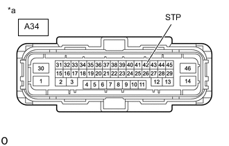
*a Front view of wire harness connector
(to Skid Control ECU (Brake Actuator Assembly))
Turn the ignition switch off.
-
Make sure that there is no looseness at the locking part and the connecting part of the connector.
OK The connector is securely connected. -
Disconnect the A34 skid control ECU (brake actuator assembly) connector.
-
Check both the connector case and the terminals for deformation and corrosion.
OK No deformation or corrosion. -
Measure the voltage according to the value(s) in the table below.
Standard Voltage Tester Connection Condition Specified Condition A34-42 (STP) - Body ground Stop light switch assembly on (Brake pedal depressed) (+BS x 0.85) to 14 V* Tech Tips
*: The minimum voltage value varies depending on the +BS terminal voltage value. The minimum voltage is 85% or more of the +BS terminal voltage.
Result Proceed to OK NG
NG
REPAIR OR REPLACE HARNESS OR CONNECTOR (STP CIRCUIT)
OK
-
-
CHECK HARNESS AND CONNECTOR (GND1 TERMINAL)
-
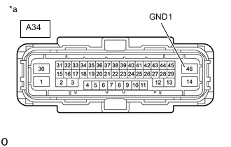
*a Front view of wire harness connector
(to Skid Control ECU (Brake Actuator Assembly))
Measure the resistance according to the value(s) in the table below.
Standard Resistance Tester Connection Condition Specified Condition A34-46 (GND1) - Body ground Always Below 1 Ω Result Proceed to OK NG
OK
REPLACE BRAKE ACTUATOR ASSEMBLY for LHD: Click here
REPLACE BRAKE ACTUATOR ASSEMBLY for RHD: Click hereNG
REPAIR OR REPLACE HARNESS OR CONNECTOR (GND1 CIRCUIT)
-
-
INSPECT STOP LIGHT SWITCH ASSEMBLY
-
Inspect the stop light switch assembly.
OK The stop light switch assembly is normal. Result Proceed to OK NG
NG
REPLACE STOP LIGHT SWITCH ASSEMBLY Click here
OK
-
-
CHECK HARNESS AND CONNECTOR (STP TERMINAL)
-
*a Front view of wire harness connector
(to Skid Control ECU (Brake Actuator Assembly))
Make sure that there is no looseness at the locking part and the connecting part of the connector.
OK The connector is securely connected. -
Disconnect the A34 skid control ECU (brake actuator assembly) connector.
-
Check both the connector case and the terminals for deformation and corrosion.
OK No deformation or corrosion. -
Measure the voltage according to the value(s) in the table below.
Standard Voltage Tester Connection Condition Specified Condition A34-42 (STP) - Body ground Stop light switch assembly on (Brake pedal depressed) (+BS x 0.85) to 14 V* A34-42 (STP) - Body ground Stop light switch assembly off (Brake pedal released) Below 1.5 V Tech Tips
*: The minimum voltage value varies depending on the +BS terminal voltage value. The minimum voltage is 85% or more of the +BS terminal voltage.
Result Proceed to OK NG
NG
REPAIR OR REPLACE HARNESS OR CONNECTOR (STP CIRCUIT)
OK
-
-
RECONFIRM DTC
-
Reconnect the A34 skid control ECU (brake actuator assembly) connector.
-
Clear the DTCs.
Chassis > ABS/VSC/TRC > Clear DTCs -
Turn the ignition switch off.
-
Start the engine.
-
Drive the vehicle at a speed of 3 km/h (2 mph) or more and depress the brake pedal several times to test the stop light circuit.
-
Check if the same DTC is output.
Chassis > ABS/VSC/TRC > Trouble CodesResult Result Proceed to C1426 is not output A C1426 is output B Tech Tips
If the lighting system is normal but the DTC is still output, replace the skid control ECU (brake actuator assembly).
for LHD: Click here
for RHD: Click here
A
USE SIMULATION METHOD TO CHECK Click here
B
INSPECT LIGHTING SYSTEM (STOP LIGHT CIRCUIT) Click here
-