VEHICLE STABILITY CONTROL SYSTEM PRECAUTION
-
PRECAUTION FOR DISCONNECTING CABLE FROM NEGATIVE BATTERY TERMINAL
Note
When disconnecting the cable from the negative (-) battery terminal, initialize the following system(s) after the cable is reconnected:
System See Procedure Lane Departure Alert System (w/ Steering Control) Parking Assist Monitor System Pre-collision System -
IGNITION SWITCH EXPRESSION
Tech Tips
The type of ignition switch used on this model differs according to the specifications of the vehicle. The expressions listed in the table below are used in this section.
Expression Ignition Switch (Position) Engine Switch (Condition) Ignition Switch off LOCK Off (Lock) Ignition Switch ACC ACC On (ACC) Ignition Switch ON ON On (IG) Engine Start START On (Start) -
TROUBLESHOOTING PRECAUTION
-
When there is a malfunction with terminal contact points or part installation problems, removal and installation of the suspected parts may return the system to normal either completely or temporarily.
-
In order to determine the malfunctioning area, be sure to check the conditions at the time the malfunction occurred, such as DTC output and Freeze Frame Data, and record it before disconnecting any connector or removing and installing parts.
-
Since the system may be influenced by malfunctions in systems other than the VSC system, be sure to check for DTCs in other systems.
-
-
HANDLING PRECAUTION
-
Do not remove or install VSC parts such as the steering angle sensor or yaw rate and acceleration sensor (airbag sensor assembly) except when required, as they need to be adjusted correctly after removal and installation.
-
Be sure to perform preparation before work and confirmation after work is completed by following the directions in the repair manual when working on the VSC system.
-
Be sure to remove and install the skid control ECU (brake actuator assembly), sensors, etc. with the ignition switch off unless it is otherwise specified in the inspection procedure.
-
If the skid control ECU (brake actuator assembly) or a sensor has been removed and installed, it is necessary to check the system for problems after the parts have been reassembled. Check for DTCs using the GTS. Also check that the system functions and signals received by the ECU are normal using Test Mode (Signal Check).
-
-
DTC PRECAUTION
-
Warnings for some DTCs cannot be cleared only by repairing the malfunctioning parts. If the warning is displayed after repair work, the DTC should be cleared after turning the ignition switch off.
Note
If a DTC for a malfunctioning part reappears after it was cleared, then it has been stored again.
-
When 2 or more DTCs are detected, perform diagnosis for each DTC, one by one until the problem is identified.
-
-
CHASSIS DYNAMOMETER PRECAUTION
When testing with a 2-wheel drum tester such as speedometer tester, combination tester for the speedometer and brakes, or chassis dynamometer, or when jacking up the front wheels and turning the wheels, perform the following procedure to enter Inspection Mode and disable the TRC and VSC systems.
CAUTION:
-
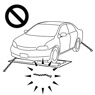
Do not use the drum tester with any of the lock chains disconnected.
-
Using the drum tester with a lock chain disconnected could cause the vehicle to begin moving unexpectedly.
-
Do not use the drum tester while the TRC or VSC is able to operate.
-
TRC or VSC operation could cause the vehicle to begin moving unexpectedly.
Note
Secure the vehicle with lock chains for safety.
-
Activating Inspection Mode (When Using the GTS)
-
Ensure that the ignition switch is off and the engine is stopped.
-
Make sure that the shift lever is in P.
-
Connect the GTS to the DLC3.
-
Start the engine.
-
Turn the GTS on.
-
Enter the following menus: Chassis / ABS/VSC/TRC / Utility / Inspection Mode.
Chassis > ABS/VSC/TRC > UtilityTester Display Inspection Mode -
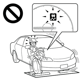
Check that the VSC OFF indicator light comes on and "Traction Control Turned Off" is displayed on the multi-information display.
Tech Tips
-
If the VSC OFF indicator light does not come on and "Traction Control Turned Off" is not displayed on the multi-information display repeat the previous steps.
-
Turning the ignition switch off ends Inspection Mode.
-
-
-
Activating Inspection Mode (When not Using the GTS)
Tech Tips
Perform steps "C" to "H" within 30 seconds.
-
Ensure that the ignition switch is off and the engine is stopped (Step "A").
-
Make sure that the shift lever is in P (Step "B").
-
Start the engine (Step "C").
-
Apply the parking brake (Step "D").
-
Depress and release the brake pedal twice (Step "E").
-
While holding the brake pedal down, release and apply the parking brake twice (Step "F").
-
With the parking brake applied, depress and release the brake pedal twice (Step "G").
-
Check that the VSC OFF indicator light comes on and "Traction Control Turned Off" is displayed on the multi-information display (Step "H").
Tech Tips
-
If the VSC OFF indicator light does not come on and "Traction Control Turned Off" is not displayed on the multi-information display in step "H", repeat steps "A" to "H".
-
Turning the ignition switch off ends Inspection Mode.
-
-
-
-
DISABLING AND ENABLING OF TRC AND VSC BY OPERATION OF VSC OFF SWITCH
-
Switching of mode
Operating the VSC OFF switch switches the system between normal mode, TRC off mode and VSC off mode.
-
Normal mode
If the VSC OFF switch is pressed when in TRC off mode or VSC off mode, the system enters normal mode.
In normal mode, TRC and VSC are enabled.
The system is set to normal mode when the ignition switch is turned to ON.
-
TRC off mode
If the VSC OFF switch is pressed when in normal mode, the system enters TRC off mode. When in TRC off mode, TRC is disabled and the multi-information display in the combination meter assembly displays "Traction Control Turned Off".
When the vehicle reaches a certain vehicle speed when in TRC off mode, the system automatically returns to normal mode.
-
VSC off mode
When the VSC OFF switch is pressed and held for 3 seconds or more with the vehicle stopped, the system enters VSC off mode. When in VSC off mode, TRC and VSC are disabled, the multi-information display in the combination meter assembly displays "Traction Control Turned Off" and the VSC OFF indicator light is illuminated.
The system does not automatically return to normal mode based on vehicle speed when in VSC off mode.
-
-
-
CAN COMMUNICATION SYSTEM PRECAUTION
-
The CAN communication system is used for communication between the skid control ECU (brake actuator assembly), steering angle sensor, yaw rate and acceleration sensor (airbag sensor assembly) and other ECUs. If there is a malfunction in a CAN communication line, communication DTCs related to the affected systems will be stored.
-
If any CAN communication DTCs are output, repair the malfunction, then troubleshoot the VSC system while communication is normal.
-
In order to enable CAN communication, a specific type of wiring is used for the CAN communication lines. The wiring used for each communication line is a twisted pair of wires that have an equal length. A bypass wire should not be used because the data being transmitted will be corrupted.
-