VEHICLE STABILITY CONTROL SYSTEM TERMINALS OF ECU
-
TERMINALS OF ECU

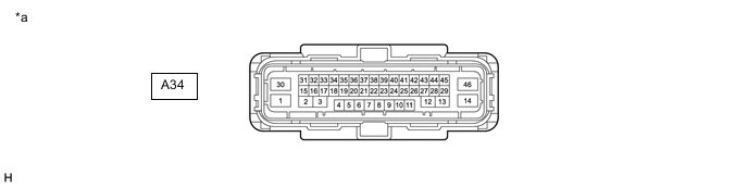
*a Component without harness connected
(Skid Control ECU (Brake Actuator Assembly))
- - Terminal No. (Symbol) Terminal Description 1 (+BM) ABS motor relay power supply 2 - 3 - 4 - 5 (CANH) CAN communication line H 6 (CSW) VSC OFF switch input 7 (FL-) Front wheel speed LH (-) signal input 8 - 9 - 10 (STPO) Stop light control relay (stop light switch assembly) output 11 - 12 - 13 - 14 (GND2) Pump motor ground 15 - 16 - 17 - 18 - 19 (CANL) CAN communication line L 20 - 21 (FR+) Front wheel speed RH (+) signal input 22 (RR+) Rear wheel speed RH (+) signal input 23 (RL-) Rear wheel speed LH (-) signal input 24 (FL+) Front wheel speed LH (+) signal input 25 - 26 (FR-) Front wheel speed RH (-) signal input 27 - 28 - 29 - 30 (+BS) ABS solenoid relay power supply 31 - 32 - 33 - 34 (SP1) Speed signal output for speedometer 35 - 36 (IG1) IG1 power source input 37 (RR-) Rear wheel speed RH (-) signal input 38 - 39 (RL+) Rear wheel speed LH (+) signal input 40 - 41 - 42 (STP) Stop light switch assembly input 43 (HZRI) Brake hold switch (electric parking brake switch assembly) input 44 (STP2) Stop light control relay (stop light switch assembly) input 45 - 46 (GND1) Skid control ECU (brake actuator assembly) ground -
TERMINAL INSPECTION
-
Disconnect the connector and measure the voltage and resistance on the wire harness side.
*a Front view of wire harness connector (to Skid Control ECU (Brake Actuator Assembly)) - - Tech Tips
The voltage cannot be measured with the connector connected to the skid control ECU (brake actuator assembly) because the connector is watertight.
Standard Terminal No. (Symbol) Wiring Color Terminal Description Condition Specified Condition A34-1 (+BM) - Body ground B - Body ground ABS motor relay power supply Always 11 to 14 V A34-6 (CSW) - Body ground P - Body ground VSC OFF switch input VSC OFF switch on → off (Pressed → not pressed) Below 1 Ω → 10 kΩ or higher A34-10 (STPO) - Body ground L - Body ground Stop light control relay (stop light switch assembly) output Always 11 to 14 V A34-14 (GND2) - Body ground W-B - Body ground Pump motor ground Always Below 1 Ω A34-30 (+BS) - Body ground G - Body ground ABS solenoid relay power supply Always 11 to 14 V A34-36 (IG1) - Body ground B - Body ground IG1 power source input Ignition switch ON 11 to 14 V A34-42 (STP) - Body ground GR - Body ground Stop light switch assembly input Stop light switch assembly on → off (Brake pedal depressed → released) (+BS x 0.85) to 14 V* → Below 1.5 V A34-43 (HZRI) - Body ground LG - Body ground Brake hold switch (electric parking brake switch assembly) input Brake hold switch (electric parking brake switch assembly) on → off (Pressed → not pressed) Below 1 Ω → 10 kΩ or higher A34-44 (STP2) - Body ground R - Body ground Stop light control relay (stop light switch assembly) input Stop light switch assembly on → off (Brake pedal depressed → released) (+BS x 0.85) to 14 V* → Below 1.5 V A34-46 (GND1) - Body ground W-B - Body ground Skid control ECU (brake actuator assembly) ground Always Below 1 Ω Tech Tips
*: The minimum voltage value varies depending on the +BS terminal voltage value. The minimum voltage is 85% or more of the +BS terminal voltage.
-