REAR SHOCK ABSORBER INSTALLATION

CAUTION / NOTICE / HINT
Tech Tips
-
Use the same procedure for the RH side and LH side.
-
The following procedure is for the LH side.
PROCEDURE
-
INSTALL REAR SUSPENSION SUPPORT ASSEMBLY
-
Secure the rear suspension support assembly in a vise using aluminum plates.
Note
Do not overtighten the vise.
-
Install the rear suspension support assembly to the rear shock absorber assembly.
-
Apply a few drops of adhesive to the threads of a new rear support to rear shock absorber nut.
Adhesive Toyota Genuine Adhesive 1324, Three Bond 1324 or equivalent -
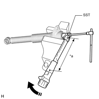
*a Torque Wrench Fulcrum Length Using SST and a 6 mm hexagon socket wrench, hold the rear shock absorber rod and tighten the rear support to rear shock absorber nut.
- SST
- 09729-97202
- Torque:
- Specified tightening torque
- 25 N*m { 255 kgf*cm, 18 ft.*lbf }
Note
Securely insert the 6 mm hexagon socket wrench into the rear shock absorber rod to prevent damage to the rear shock absorber assembly when tightening the rear support to rear shock absorber nut.
Tech Tips
-
Calculate the torque wrench reading when changing the fulcrum length of the torque wrench.
-
When using SST (fulcrum length of 40 mm (1.57 in.)) + torque wrench (fulcrum length of 180 mm (7.09 in.)):
20 N*m (204 kgf*cm, 15 ft.*lbf)
-
-
INSTALL REAR SHOCK ABSORBER CAP
-
Install the rear shock absorber cap to the rear shock absorber assembly.
-
-
TEMPORARILY INSTALL REAR SHOCK ABSORBER ASSEMBLY
-
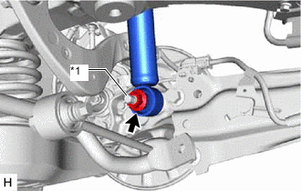
*1 Rear Axle Carrier Pin Temporarily install the rear shock absorber assembly to the rear axle carrier sub-assembly with the nut and plate washer.
Note
Hold the rear axle carrier pin while rotating the nut.
-
-
STABILIZE SUSPENSION
-
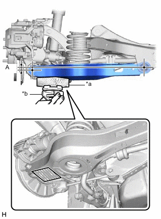
*a Wooden Block *b Jack 
Wooden Block Placement Location Using a jack and a wooden block, apply load to the suspension so that the rear No. 2 suspension arm assembly is positioned as shown in the illustration.
Standard Length (A) 13 mm (0.512 in.) CAUTION:
Do not jack up the rear No. 2 suspension arm assembly too high as the vehicle may fall.
Note
-
When jacking up the rear No. 2 suspension arm assembly, be sure to jack it up slowly.
-
Make sure to perform this operation with the vehicle kept as low as possible.
-
-
-
INSTALL REAR UPPER CONTROL ARM ASSEMBLY
-
Install the rear upper control arm assembly to the rear axle carrier sub-assembly with the bolt and nut.
- Torque:
- 73 N*m { 744 kgf*cm, 54 ft.*lbf }
Note
-
Insert the bolt with the threaded end facing the rear of the vehicle.
-
Because the nut has its own stopper, do not turn the nut. Tighten the bolt with the nut secured.
-
-
CONNECT REAR SHOCK ABSORBER ASSEMBLY
-
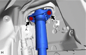
Connect the rear shock absorber assembly to the vehicle with the 2 bolts.
- Torque:
- 55 N*m { 561 kgf*cm, 41 ft.*lbf }
Note
Temporarily tighten the bolt (A) and then fully tighten the 2 bolts in the order of (B) and (A).
-
-
INSTALL REAR SHOCK ABSORBER ASSEMBLY
-
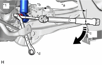
*1 Rear Axle Carrier Pin *a Torque Wrench Fulcrum Length *b Ball Joint Lock Nut Wrench *c Turn *d Hold Using a ball joint lock nut wrench fully tighten the rear shock absorber assembly with the nut.
- Torque:
- Specified tightening torque
- 125 N*m { 1275 kgf*cm, 92 ft.*lbf }
Note
Hold the rear axle carrier pin while rotating the nut.
Tech Tips
-
Calculate the torque wrench reading when changing the fulcrum length of the torque wrench.
-
When using a ball joint lock nut wrench (fulcrum length of 149.75 mm (5.90 in.)) + torque wrench (fulcrum length of 400 mm (1.31 ft.)):
91 N*m (928 kgf*cm, 67 ft.*lbf)
-
-
INSTALL REAR STABILIZER LINK ASSEMBLY
-
INSTALL NO. 1 FLOOR UNDER COVER (w/ Cover)
-
for RH Side:
-
-
INSTALL NO. 2 FLOOR UNDER COVER (w/ Cover)
-
for LH Side:
-
-
INSTALL REAR HEIGHT CONTROL SENSOR SUB-ASSEMBLY LH (for LH Side)
-
INSTALL REAR WHEEL
-
INSPECT AND ADJUST REAR WHEEL ALIGNMENT
-
PERFORM INITIALIZATION
Parking assist monitor system Click here for Initialization
Click here for Calibration
Lighting system (EXT)