REAR SHOCK ABSORBER REMOVAL

CAUTION / NOTICE / HINT
The necessary procedures (adjustment, calibration, initialization, or registration) that must be performed after parts are removed and installed, or replaced during rear shock absorber assembly removal/installation are shown below.
| Replaced Part or Performed Procedure | Necessary Procedure | Effect/Inoperative Function when Necessary Procedure not Performed | Link |
|---|---|---|---|
| Rear wheel alignment adjustment | Perform system variant learning and acceleration sensor zero point calibration. |
|
|
| Suspension, tires (The vehicle height changes because of suspension or tire replacement.) |
Rear television camera assembly optical axis (Back camera position setting) | Parking assist monitor system | Click here for Initialization Click here for Calibration |
| Perform headlight ECU sub-assembly LH initialization | Lighting System (EXT) (w/ Automatic Headlight Beam Level Control System) | ||
| Rear height control sensor sub-assembly LH | Perform headlight ECU sub-assembly LH initialization | Lighting System (EXT) (w/ Automatic Headlight Beam Level Control System) |
Tech Tips
-
Use the same procedure for the RH side and LH side.
-
The following procedure is for the LH side.
PROCEDURE
-
REMOVE REAR WHEEL
-
REMOVE NO. 2 FLOOR UNDER COVER (w/ Cover)
-
for LH Side:
-
-
REMOVE NO. 1 FLOOR UNDER COVER (w/ Cover)
-
for RH Side:
-
-
REMOVE REAR HEIGHT CONTROL SENSOR SUB-ASSEMBLY LH (w/ Height Control Sensor)
-
for LH Side:
-
-
LOOSEN REAR SHOCK ABSORBER ASSEMBLY
-
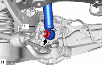
*1 Rear Axle Carrier Pin Loosen the nut of the rear shock absorber assembly.
Note
Hold the rear axle carrier pin while rotating the nut.
-
-
REMOVE REAR STABILIZER LINK ASSEMBLY
-
SEPARATE REAR SHOCK ABSORBER ASSEMBLY
-
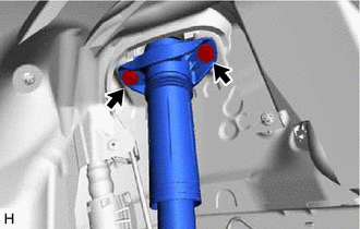
Remove the 2 bolts and separate the rear shock absorber assembly from the vehicle.
-
-
SEPARATE REAR UPPER CONTROL ARM ASSEMBLY
-
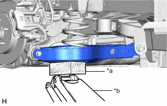
*a Wooden Block *b Jack Using a jack and a wooden block, support the rear No. 2 suspension arm assembly.
Note
-
When jacking up the rear No. 2 suspension arm assembly, be sure to jack it up slowly.
-
Make sure to perform this operation with the vehicle kept as low as possible.
-
-
Remove the bolt and nut, and separate the rear upper control arm assembly from the rear axle carrier sub-assembly.
Note
Because the nut has its own stopper, do not turn the nut. Loosen the bolt with the nut secured.
-
-
REMOVE REAR SHOCK ABSORBER ASSEMBLY
-

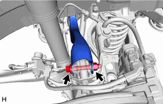
*1 Rear Axle Carrier Pin Remove the nut, plate washer and rear shock absorber assembly from the rear axle carrier sub-assembly.
Note
Hold the rear axle carrier pin while rotating the nut.
-
-
REMOVE REAR SHOCK ABSORBER CAP
-
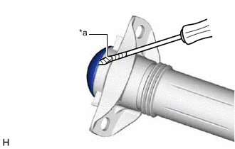
*a Protective Tape Using a screwdriver with its tip wrapped with protective tape, remove the rear shock absorber cap from the rear shock absorber assembly.
-
-
REMOVE REAR SUSPENSION SUPPORT ASSEMBLY
-
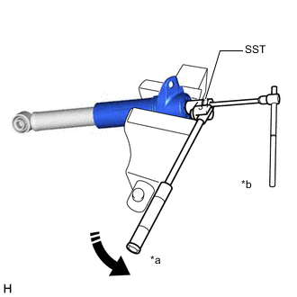
*a Turn *b Hold Secure the rear shock absorber assembly in a vise using aluminum plates.
Note
Do not overtighten the vise.
-
Using SST and a 6 mm hexagon socket wrench, hold the rear shock absorber rod and remove the rear support to rear shock absorber nut.
- SST
- 09729-97202
-
Remove the rear suspension support assembly from the rear shock absorber assembly.
-