FRONT SUSPENSION MEMBER REMOVAL

CAUTION / NOTICE / HINT
The necessary procedures (adjustment, calibration, initialization, or registration) that must be performed after parts are removed and installed, or replaced during front frame assembly removal/installation are shown below.
| Replaced Part or Performed Procedure | Necessary Procedure | Effect/Inoperative Function when Necessary Procedure not Performed | Link |
|---|---|---|---|
| Battery terminal is disconnected/reconnected | Perform steering sensor zero point calibration | Lane departure alert system (w/ Steering Control) | |
| Pre-collision system | |||
| Memorize steering angle neutral point | Parking assist monitor system | ||
| Replacement of ECM | Vehicle Identification Number (VIN) registration | MIL comes on | for 2AR-FE: Click here for A25A-FKS (w/ Canister Pump Module): Click here for A25A-FKS (w/o Canister Pump Module): Click here for 2GR-FKS: Click here |
| Perform code registration (Immobiliser system) | Engine start function | See Service Bulletin for the registration method. | |
|
Inspection After Repair |
|
for 2AR-FE: Click here for A25A-FKS (w/ Canister Pump Module): Click here for A25A-FKS (w/o Canister Pump Module): Click here for 2GR-FKS: Click here |
| Replacement of automatic transaxle assembly |
|
|
for UA80E Initialization: Click here for UA80E Registration: Click here for UB80E Initialization: Click here for UB80E Registration: Click here for U760E Initialization: Click here for U760E Registration: Click here |
| Replacement of ECM (If possible, read the transaxle compensation code from the previous ECM) |
|
||
| Replacement of ECM (If impossible, read the transaxle compensation code from the previous ECM) |
|
||
| Replacement of ECM | Perform code registration (Immobiliser function) |
|
See Service Bulletin for the registration method. |
| Suspension, tires, etc. (The vehicle height changes because of suspension or tire replacement) |
Rear television camera assembly optical axis (Back camera position setting) | Parking assist monitor system | for Initialization: Click here for Calibration: Click here |
| Perform headlight ECU sub-assembly LH initialization | Lighting system (EXT) (w/ Automatic Headlight Beam Level Control System) | ||
| Front wheel alignment adjustment | Perform system variant learning and acceleration sensor zero point calibration. |
|
|
| Rack and pinion power steering gear assembly |
|
|
PROCEDURE
-
REMOVE ENGINE ASSEMBLY WITH TRANSAXLE
for 2AR-FE: Click here
for A25A-FKS: Click here
for 2GR-FKS: Click here
-
REMOVE FUEL DELIVERY GUARD (for A25A-FKS)
-
INSTALL ENGINE HANGER
for 2AR-FE: Click here
for A25A-FKS: Click here
for 2GR-FKS: Click here
-
REMOVE STEERING GEAR HEAT INSULATOR (for LHD)
for A25A-FKS Click here
-
DISCONNECT WIRE HARNESS
for LHD: Click here
for RHD: Click here
-
REMOVE FRONT FRAME ASSEMBLY
-
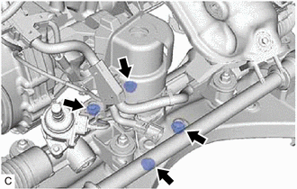
Remove the 3 nuts and separate the front engine mounting insulator from the front frame assembly.
-
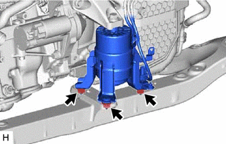
Remove the 4 nuts and separate the rear engine mounting insulator from the front frame assembly.
-
-
REMOVE FRONT STABILIZER BAR WITH BRACKET
for A25A-FKS: Click here
for 2AR-FE, 2GR-FKS: Click here
-
REMOVE RACK AND PINION POWER STEERING GEAR ASSEMBLY
-
REMOVE FRONT LOWER NO. 1 SUSPENSION ARM SUB-ASSEMBLY LH
-
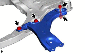
Remove the 3 bolts, nut and front lower No. 1 suspension arm sub-assembly LH from the front frame assembly.
Note
Because the nut has its own stopper, do not turn the nut. Loosen the bolt with the nut secured.
-
Remove the front lower arm bushing stopper from the front lower No. 1 suspension arm sub-assembly.
-
-
REMOVE FRONT LOWER NO. 1 SUSPENSION ARM SUB-ASSEMBLY RH
Tech Tips
Perform the same procedure as for the LH side.
-
REMOVE NO. 2 EXHAUST PIPE SUPPORT BRACKET
-
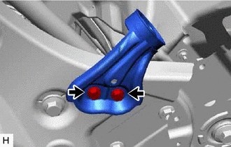
Remove the 2 bolts and No. 2 exhaust pipe support bracket from the front frame assembly.
-
-
REMOVE FRONT SUSPENSION MEMBER DYNAMIC DAMPER (for A25A-FKS, 2GR-FKS)
-
Remove the 2 bolts and front suspension member dynamic damper from the front frame assembly.
-
-
REMOVE BOLT (for 2AR-FE)
-
Remove the 2 bolts from the front frame assembly.
-
-
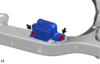
REMOVE FRONT SUSPENSION MEMBER BODY MOUNTING FRONT STOPPER
-
Remove the 2 front suspension member body mounting front stoppers from the front frame assembly.
-
-
REMOVE FRONT SUSPENSION MEMBER BODY MOUNTING REAR STOPPER
-
Remove the 2 front suspension member body mounting rear stoppers from the front frame assembly.
-
-
REMOVE FRONT SUSPENSION MEMBER BODY MOUNTING FRONT CUSHION (for LH Side)
-
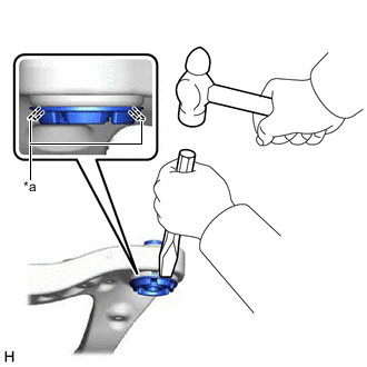
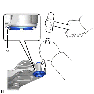
*a Flange Using a chisel and hammer, kink the flange of the front suspension member body mounting front cushion as shown in the illustration.
-
Apply lubricant to the contact surfaces of the front suspension member body mounting front cushion.
-
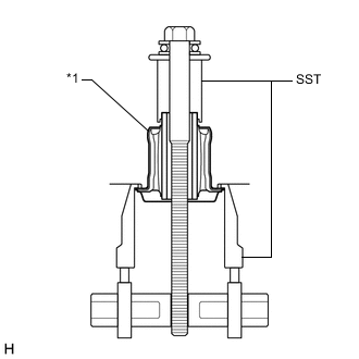
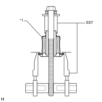
*1 Front Suspension Member Body Mounting Front Cushion Install SST as shown in the illustration.
- SST
- 09830-10010 ( 09830-01010, 09830-01040, 09830-01050 )
- 09950-40011 ( 09951-04020, 09952-04010, 09954-04010, 09955-04011, 09958-04011 )
Note
Apply molybdenum grease to the threads and tip of the SST center bolt before use.
-
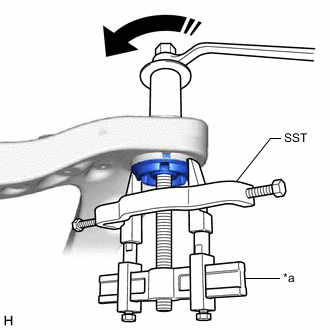
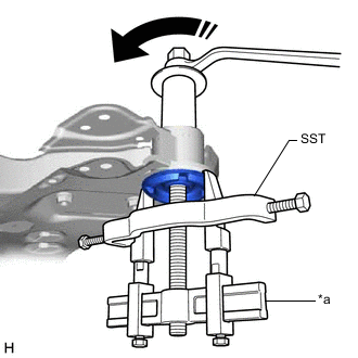
*a Hold 
Turn Turn the SST center bolt as shown in the illustration to create a clearance between the front suspension member body mounting front cushion and the front frame assembly.
-
While applying lubricant to the front suspension member body mounting front cushion through the clearance, gradually remove the front suspension member body mounting front cushion.
Note
-
Tighten SST slowly and evenly.
-
Be careful as the mounting cushion may fly out.
-
The mounting cushion cannot be reused.
-
-
-
REMOVE FRONT SUSPENSION MEMBER BODY MOUNTING FRONT CUSHION (for RH Side)
Tech Tips
Perform the same procedure as for the LH side.
-
REMOVE FRONT SUSPENSION MEMBER BODY MOUNTING REAR CUSHION LH
-
*a Flange Using a chisel and hammer, kink the flange of the front suspension member body mounting rear cushion LH as shown in the illustration.
-
Apply lubricant to the contact surfaces of the front suspension member body mounting rear cushion LH.
-
*1 Front Suspension Member Body Mounting Rear Cushion LH Install SST as shown in the illustration.
- SST
- 09830-10010 ( 09830-01010, 09830-01040, 09830-01050 )
- 09950-40011 ( 09951-04020, 09952-04010, 09954-04010, 09955-04011, 09958-04011 )
Note
Apply molybdenum grease to the threads and tip of the SST center bolt before use.
-
*a Hold Turn Turn the SST center bolt as shown in the illustration to create a clearance between the front suspension member body mounting rear cushion LH and the front frame assembly.
-
While applying lubricant to the front suspension member body mounting rear cushion LH through the clearance, gradually remove the front suspension member body mounting rear cushion LH.
Note
-
Tighten SST slowly and evenly.
-
Be careful as the mounting cushion may fly out.
-
The mounting cushion cannot be reused.
-
-
-
REMOVE FRONT SUSPENSION MEMBER BODY MOUNTING REAR CUSHION
Tech Tips
Perform the same procedure as for the front suspension member body mounting rear cushion LH.
-
REMOVE HOLE PLUG
-
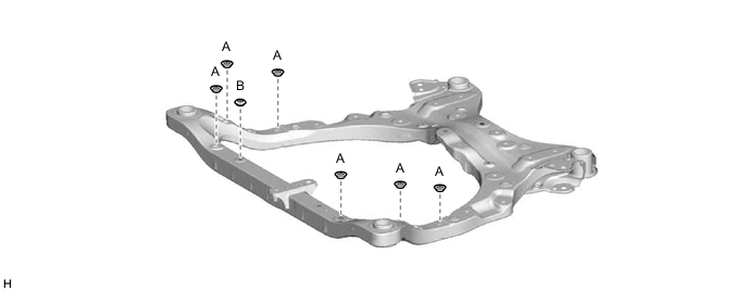
Remove the 7 hole plugs from the front frame assembly.
Tech Tips
There are 2 different shapes of hole plug.
-