FRONT LOWER SUSPENSION ARM(for A25A-FKS, 2GR-FKS) REMOVAL
CAUTION / NOTICE / HINT
The necessary procedures (adjustment, calibration, initialization, or registration) that must be performed after parts are removed and installed, or replaced during front lower No. 1 suspension arm sub-assembly removal/installation are shown below.
| Replaced Part or Performed Procedure | Necessary Procedure | Effect/Inoperative Function when Necessary Procedure not Performed | Link |
|---|---|---|---|
| Front wheel alignment adjustment | Perform system variant learning and acceleration sensor zero point calibration. |
|
|
| Suspension, tires, etc. (The vehicle height changes because of suspension or tire replacement) |
Rear television camera assembly optical axis (Back camera position setting) | Parking assist monitor system | for Initialization: Click here for Calibration: Click here |
| Perform headlight ECU sub-assembly LH initialization | Lighting system (EXT) |
Tech Tips
-
Use the same procedure for the RH side and LH side.
-
The following procedure is for the LH side.
PROCEDURE
-
REMOVE FRONT WHEEL
-
REMOVE FRONT WHEEL OPENING EXTENSION PAD LH (for A25A-FKS)
-
REMOVE FRONT WHEEL OPENING EXTENSION PAD RH (for A25A-FKS)
-
REMOVE NO. 1 ENGINE UNDER COVER (for A25A-FKS)
-
REMOVE NO. 2 ENGINE UNDER COVER ASSEMBLY (for A25A-FKS)
-
REMOVE FRONT FLOOR COVER LH (for A25A-FKS)
-
REMOVE FRONT FENDER APRON SEAL LH
for A25A-FKS: Click here
for 2GR-FKS: Click here
-
REMOVE FRONT LOWER NO. 1 SUSPENSION ARM SUB-ASSEMBLY
-
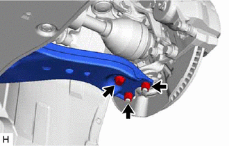
Remove the bolt and 2 nuts and separate the front lower No. 1 suspension arm sub-assembly from the front lower ball joint assembly.
-
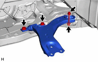
Remove the 3 bolts, nut and front lower No. 1 suspension arm sub-assembly from the front frame assembly.
Note
Because the nut has its own stopper, do not turn the nut. Loosen the bolt with the nut secured.
-
Remove the front lower arm bushing stopper from the front lower No. 1 suspension arm sub-assembly.
-