FRONT LOWER SUSPENSION ARM(for 2AR-FE LH Side) REMOVAL
CAUTION / NOTICE / HINT
The necessary procedures (adjustment, calibration, initialization, or registration) that must be performed after parts are removed and installed, or replaced during front lower No. 1 suspension arm sub-assembly LH removal/installation are shown below.
| Replaced Part or Performed Procedure | Necessary Procedure | Effect/Inoperative Function when Necessary Procedure not Performed | Link |
|---|---|---|---|
| Front wheel alignment adjustment | Perform system variant learning and acceleration sensor zero point calibration. |
|
|
| Suspension, tires, etc. (The vehicle height changes because of suspension or tire replacement) |
Rear television camera assembly optical axis (Back camera position setting) | Parking assist monitor system | for Initialization: Click here for Calibration: Click here |
| Perform headlight ECU sub-assembly LH initialization | Lighting system (EXT) |
PROCEDURE
-
REMOVE FRONT WHEEL
-
REMOVE FRONT WHEEL OPENING EXTENSION PAD LH
-
REMOVE FRONT WHEEL OPENING EXTENSION PAD RH
-
REMOVE NO. 1 ENGINE UNDER COVER
-
REMOVE FRONT FENDER APRON SEAL LH
-
REMOVE AIR CLEANER ASSEMBLY
-
REMOVE BATTERY
-
REMOVE BATTERY CLAMP SUB-ASSEMBLY
-
SEPARATE FRONT LOWER NO. 1 SUSPENSION ARM SUB-ASSEMBLY LH
-
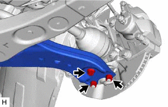
Remove the bolt and 2 nuts and separate the front lower No. 1 suspension arm sub-assembly LH from the front lower ball joint assembly LH.
-
-
SEPARATE FRONT ENGINE MOUNTING INSULATOR
-
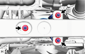
Remove the 3 nuts and separate the front engine mounting insulator from the front frame assembly.
-
-
REMOVE FRONT LOWER NO. 1 SUSPENSION ARM SUB-ASSEMBLY LH
-
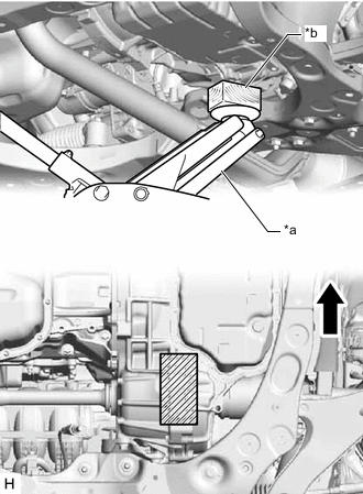
*a Jack *b Wooden Block 
Front of the Vehicle 
Wooden Block Placement Location Using a jack and wooden block, support the engine assembly with transaxle at the position shown in the illustration.
Note
-
Do not position the wooden block under the oil pan.
-
Ensure that the jack and wooden block are stable.
-
-
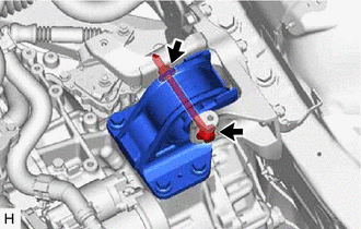
Remove the bolt and nut and separate the engine mounting insulator LH from the engine mounting bracket sub-assembly LH.
-
While ensuring that there is no interference from the components surrounding the engine, tilt the engine assembly with transaxle to a position that allows the front lower No. 1 suspension arm sub-assembly LH bolt.
Note
-
Do not damage the components surrounding the engine assembly with transaxle.
-
Tilt the engine assembly with transaxle as little as possible.
-
Keep the engine assembly with transaxle supported until installation of the front lower No. 1 suspension arm sub-assembly LH.
-
-
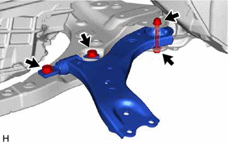
Remove the 3 bolts, nut and front lower No. 1 suspension arm sub-assembly LH from the front frame assembly.
Note
Because the nut has its own stopper, do not turn the nut. Loosen the bolt with the nut secured.
-
Remove the front lower arm bushing stopper from the front lower No. 1 suspension arm sub-assembly LH.
-