CAUTION / NOTICE / HINT
The necessary procedures (adjustment, calibration, initialization, or registration) that must be performed after completing the rear wheel alignment procedure are shown below.
| Replaced Part or Performed Procedure | Necessary Procedure | Effect/Inoperative Function when Necessary Procedure not Performed | Link |
|---|---|---|---|
| Rear wheel alignment adjustment | Perform system variant learning and acceleration sensor zero point calibration. |
|
PROCEDURE
- Click here
PRECAUTION
As the standard wheel alignment values differ depending on the suspension type, refer to the following table to confirm the suspension type for each model.
MODEL CODE SUSPENSION TYPE ASV70R-AETDKQ NORMAL ASV70R-AETNKQ NORMAL ASV70R-AETVKQ SPORT GSV70R-AEZNBQ NORMAL GSV70R-AEZVBQ SPORT AXVA70L-AEZDBV NORMAL AXVA70L-AEZNBV NORMAL AXVA70L-AEZSBV SPORT ASV70L-AETDKV NORMAL ASV70L-AETNKV NORMAL ASV70L-AETSKV SPORT GSV70L-AEZGBV NORMAL GSV70L-AEZSBV SPORT ASV70L-AETNKW NORMAL AXVA70L-AEZNBW NORMAL GSV70L-AEZGBW NORMAL ASV70R-AETNKW NORMAL - Click here
INSPECT TIRES
- Click here
MEASURE VEHICLE HEIGHT
- Click here
INSPECT CAMBER
Note:Inspect while the vehicle is unloaded.
-
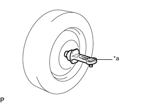
*a Camber-caster-kingpin Gauge Install a camber-caster-kingpin gauge.
-
Inspect the camber.
Camber (Unloaded Vehicle) *: for Rough Road Area Specification VehiclesEngine SUSPENSION TYPE Camber Inclination Right-left Difference 2AR-FE
A25A-FKS
NORMAL -1°10' +/- 0°45' (-1.17° +/- 0.75°)
-0°55' +/- 0°45' (-0.92° +/- 0.75°)*
0°45' (0.75°) or less SPORT -1°05' +/- 0°45' (-1.08° +/- 0.75°) 2GR-FKS NORMAL -1°10' +/- 0°45' (-1.17° +/- 0.75°)
-1°00' +/- 0°45' (-1.00° +/- 0.75°)*
SPORT -1°10' +/- 0°45' (-1.17° +/- 0.75°) Tip:Camber is not adjustable. If the measurement is not within the specified range, inspect the suspension parts for damage and/or wear, and replace them if necessary.
-
- Click here
INSPECT TOE-IN
Note:Inspect while the vehicle is unloaded.
-
Bounce the vehicle up and down at the corners to stabilize the suspension.
-
Release the parking brake and move the shift lever to N.
-
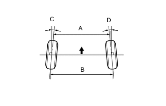
Push the vehicle straight ahead approximately 5 m (16.4 ft.). (Step A)
-
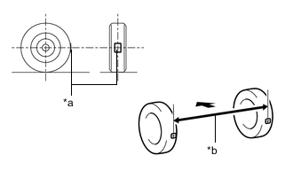
*a Tread Center Mark *b Dimension B 
Front of the Vehicle Put tread center marks on the rearmost points of the rear wheels and measure the distance between the marks (dimension B).
-
Slowly push the vehicle straight ahead to cause the rear wheels to rotate 180°. Use the rear tire valve as a reference point.
Tip:Do not allow the wheels to rotate more than 180°. If the wheels rotate more than 180°, perform the procedure from step A again.
-
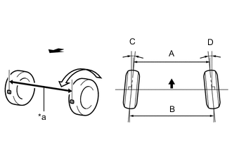
*a Dimension A Front of the Vehicle Measure the distance between the tread center marks on the front of the rear wheels (dimension A).
Toe-in (Unloaded Vehicle) *: for Rough Road Area Specification VehiclesEngine SUSPENSION TYPE Specified Condition Right-left Difference 2AR-FE
A25A-FKS
NORMAL C + D: 0°10' +/- 0°10' (0.16° +/- 0.17°)
C + D: 0°09' +/- 0°10' (0.15° +/- 0.17°)*
- B - A: 1.9 +/- 2.0 mm (0.0748 +/- 0.0787 in.)
B - A: 1.8 +/- 2.0 mm (0.0709 +/- 0.0787 in.)*
1.0 mm (0.0394 in.) or less SPORT C + D: 0°09' +/- 0°10' (0.15° +/- 0.17°) - B - A: 1.7 +/- 2.0 mm (0.0669 +/- 0.0787 in.) 1.0 mm (0.0394 in.) or less 2GR-FKS NORMAL C + D: 0°12' +/- 0°10' (0.20° +/- 0.17°)
C + D: 0°11' +/- 0°10' (0.18° +/- 0.17°)*
- B - A: 2.3 +/- 2.0 mm (0.0906 +/- 0.0787 in.)
B - A: 2.1 +/- 2.0 mm (0.0827 +/- 0.0787 in.)*
1.0 mm (0.0394 in.) or less SPORT C + D: 0°10' +/- 0°10' (0.16° +/- 0.17°) - B - A: 1.9 +/- 2.0 mm (0.0748 +/- 0.0787 in.) 1.0 mm (0.0394 in.) or less Tip:Measure "B - A" only when "C + D" cannot be measured.
If the toe-in is not within the specified range, adjust it at the rear suspension toe adjust cam sub-assembly.
-
- Click here
ADJUST TOE-IN
-
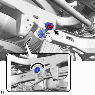
Loosen the nut of the rear No. 2 suspension arm assembly (on the rear suspension member sub-assembly side).
Note:Hold the rear suspension toe adjust cam sub-assembly while rotating the nut.
-
Front of the Vehicle Rotate the rear suspension toe adjust cam sub-assembly to adjust the toe-in.
Toe-in (Unloaded Vehicle) *: for Rough Road Area Specification VehiclesEngine SUSPENSION TYPE Specified Condition Right-left Difference 2AR-FE
A25A-FKS
NORMAL C + D: 0°10' +/- 0°10' (0.16° +/- 0.17°)
C + D: 0°09' +/- 0°10' (0.15° +/- 0.17°)*
- B - A: 1.9 +/- 2.0 mm (0.0748 +/- 0.0787 in.)
B - A: 1.8 +/- 2.0 mm (0.0709 +/- 0.0787 in.)*
1.0 mm (0.0394 in.) or less SPORT C + D: 0°09' +/- 0°10' (0.15° +/- 0.17°) - B - A: 1.7 +/- 2.0 mm (0.0669 +/- 0.0787 in.) 1.0 mm (0.0394 in.) or less 2GR-FKS NORMAL C + D: 0°12' +/- 0°10' (0.20° +/- 0.17°)
C + D: 0°11' +/- 0°10' (0.18° +/- 0.17°)*
- B - A: 2.3 +/- 2.0 mm (0.0906 +/- 0.0787 in.)
B - A: 2.1 +/- 2.0 mm (0.0827 +/- 0.0787 in.)*
1.0 mm (0.0394 in.) or less SPORT C + D: 0°10' +/- 0°10' (0.16° +/- 0.17°) - B - A: 1.9 +/- 2.0 mm (0.0748 +/- 0.0787 in.) 1.0 mm (0.0394 in.) or less Tip:
-
Rotating the rear suspension toe adjust cam sub-assembly by one notch changes the toe by approximately 2.6 mm (0.102 in.).
-
Perform adjustments so that the value is as close as possible to the median of the specified range.
-
-
Tighten the nut of the rear No. 2 suspension arm assembly (on the rear suspension member sub-assembly side).
100 N*m 1020 kgf*cm 74 ft.*lbf Note:Hold the rear suspension toe adjust cam sub-assembly while rotating the nut.
-
- Click here
ALIGN FRONT WHEELS FACING STRAIGHT AHEAD
- Click here
PERFORM SYSTEM VARIANT LEARNING AND ACCELERATION SENSOR ZERO POINT CALIBRATION