REAR AXLE CARRIER REMOVAL
CAUTION / NOTICE / HINT
The necessary procedures (adjustment, calibration, initialization, or registration) that must be performed after parts are removed and installed, or replaced during rear axle carrier sub-assembly removal/installation are shown below.
| Replaced Part or Performed Procedure | Necessary Procedure | Effect/Inoperative Function when Necessary Procedure not Performed | Link |
|---|---|---|---|
| Rear wheel alignment adjustment | Perform system variant learning and acceleration sensor zero point calibration. |
|
|
| Suspension, tires (The vehicle height changes because of suspension or tire replacement.) |
Rear television camera assembly optical axis (Back camera position setting) | Parking assist monitor system | Click here for Initialization Click here for Calibration |
| Perform headlight ECU sub-assembly LH initialization | Lighting system (EXT) | ||
| Rear height control sensor sub-assembly LH | Perform headlight ECU sub-assembly LH initialization | Lighting system (EXT) |
Tech Tips
-
Use the same procedure for the RH side and LH side.
-
The following procedure is for the LH side.
PROCEDURE
-
REMOVE REAR WHEEL
-
REMOVE NO. 2 FLOOR UNDER COVER (w/ Cover)
-
for LH Side:
-
-
REMOVE NO. 1 FLOOR UNDER COVER (w/ Cover)
-
for RH Side:
-
-
SEPARATE NO. 2 PARKING BRAKE WIRE ASSEMBLY
-
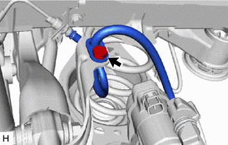
Disconnect the No. 2 parking brake wire assembly connector from the parking brake actuator assembly.
Note
-
Remove any dirt or foreign matter on and around the No. 2 parking brake wire assembly connector before performing this step.
-
Do not allow water, oil or dirt to enter the No. 2 parking brake wire assembly connector.
-
-
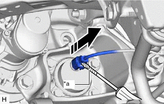
*a Protective Tape Using a screwdriver with its tip wrapped with protective tape, disconnect the No. 2 parking brake wire assembly connector from the rear axle hub and bearing assembly.
Note
Be careful not to damage the rear axle hub and bearing assembly or connector cover.
-
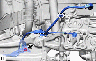
Remove the nut, disengage the 2 clamps and separate the No. 2 parking brake wire assembly from the rear flexible hose bracket and rear trailing arm assembly.
-
-
SEPARATE REAR FLEXIBLE HOSE
-
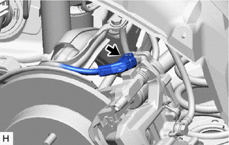
Remove the bolt and separate the rear flexible hose from the rear flexible hose bracket.
-
-
SEPARATE REAR DISC BRAKE CALIPER ASSEMBLY
-
REMOVE REAR DISC
-
REMOVE REAR AXLE HUB AND BEARING ASSEMBLY
-
REMOVE REAR FLEXIBLE HOSE BRACKET
-
Remove the bolt and rear flexible hose bracket from the rear axle carrier sub-assembly.
-
-
REMOVE REAR HEIGHT CONTROL SENSOR SUB-ASSEMBLY LH (for LH Side)
-
REMOVE REAR STABILIZER LINK ASSEMBLY
-
REMOVE REAR COIL SPRING
-
REMOVE REAR LOWER COIL SPRING INSULATOR
-
REMOVE REAR NO. 1 SUSPENSION ARM ASSEMBLY
-
REMOVE REAR AXLE CARRIER SUB-ASSEMBLY
-
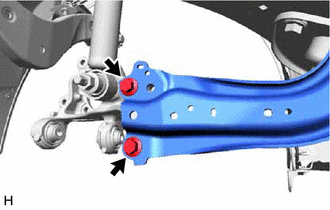
Loosen the 2 bolts of the rear trailing arm assembly.
-
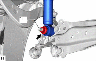
*1 Rear Axle Carrier Pin Loosen the nut of the rear shock absorber assembly.
Note
Hold the rear axle carrier pin while rotating the nut.
-
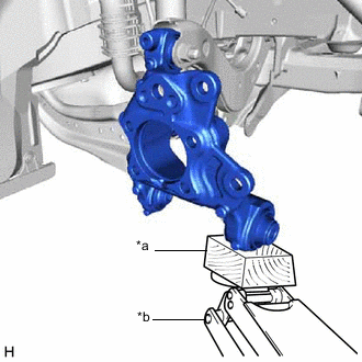
*a Wooden Block *b Jack Using a jack and a wooden block, support the rear axle carrier sub-assembly.
Note
-
When jacking up the rear axle carrier sub-assembly, be sure to jack it up slowly.
-
Make sure to perform this operation with the vehicle kept as low as possible.
-
-
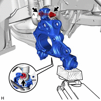
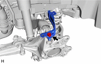
Loosen the bolt (A).
Note
Because the nut has its own stopper, do not turn the nut. Loosen the bolt with the nut secured.
-
Remove the 2 bolts and separate the rear trailing arm assembly from the rear axle carrier sub-assembly.
-
Remove the nut and plate washer, and separate the rear shock absorber assembly from the rear axle carrier sub-assembly.
Note
Hold the rear axle carrier pin while rotating the nut.
-
Remove the bolt (A), nut and rear axle carrier sub-assembly from the rear upper control arm assembly.
Note
Because the nut has its own stopper, do not turn the nut. Loosen the bolt with the nut secured.
-