CAUTION / NOTICE / HINT
The necessary procedures (adjustment, calibration, initialization, or registration) that must be performed after parts are removed and installed, or replaced during front lower ball joint assembly removal/installation are shown below.
| Replaced Part or Performed Procedure | Necessary Procedure | Effect/Inoperative Function when Necessary Procedure not Performed | Link |
|---|---|---|---|
| Front wheel alignment adjustment | Perform system variant learning and acceleration sensor zero point calibration. |
|
-
Use the same procedure for the RH side and LH side.
-
The following procedure is for the LH side.
PROCEDURE
- Click here
REMOVE FRONT AXLE ASSEMBLY
- Click here
REMOVE FRONT LOWER BALL JOINT ASSEMBLY
-
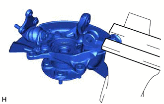
Secure the front axle assembly in a vise using aluminum plates.
Note:Do not overtighten the vise.
-
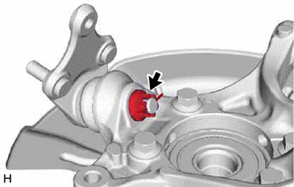
Remove the cotter pin.
-
Remove the nut.
-
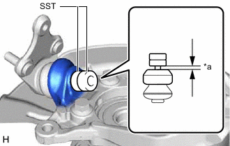
*a 1 mm (0.0394 in.) Install SST to the front lower ball joint assembly as shown in the illustration.
09960-20010 09961-02050 Note:Check that the clearance measurement between SST and the front axle assembly is 1 mm (0.0394 in.).
-
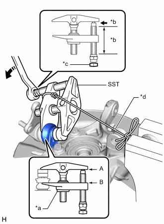
*a Center Nut *b Molybdenum Grease Application Area *c Place wrench here *d String 
Turn Using SST, remove the front lower ball joint assembly from the front axle assembly as shown in the illustration.
09960-20010 09961-02010 09961-02050 CAUTION:Apply molybdenum grease to the threads and end of the SST bolt.
Note:
-
Be sure to tighten the string firmly to secure SST to the front axle assembly to prevent SST from falling off.
-
Install SST with the center nut so that (A) and (B) shown in the illustration are parallel. Otherwise, the front lower ball joint dust cover may be damaged.
-
Be sure to place a wrench on the part shown in the illustration.
-
Do not damage the front lower ball joint dust cover.
-
Do not damage the steering knuckle.
-
Do not damage the front disc brake dust cover.
-
-