FRONT LOWER SUSPENSION ARM(for A25A-FKS, 2GR-FKS) INSTALLATION
CAUTION / NOTICE / HINT
Tech Tips
-
Use the same procedure for the RH side and LH side.
-
The following procedure is for the LH side.
PROCEDURE
-
INSTALL FRONT LOWER NO. 1 SUSPENSION ARM SUB-ASSEMBLY
-
Install the front lower arm bushing stopper to the front lower No. 1 suspension arm sub-assembly.
-
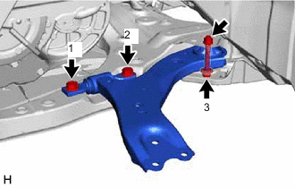
Install the front lower No. 1 suspension arm sub-assembly to the front frame assembly with the 3 bolts and nut in the order shown in the illustration.
- Torque:
- Bolt (1), (2)
- 200 N*m { 2039 kgf*cm, 148 ft.*lbf }
- Bolt (3)
- 135 N*m { 1377 kgf*cm, 100 ft.*lbf }
Note
Because the nut has its own stopper, do not turn the nut. Tighten the bolt with the nut secured.
-
Connect the front lower No. 1 suspension arm sub-assembly to the front lower ball joint assembly with the bolt and 2 nuts.
- Torque:
- 92 N*m { 938 kgf*cm, 68 ft.*lbf }
-
-
INSTALL FRONT FENDER APRON SEAL LH
for A25A-FKS: Click here
for 2GR-FKS: Click here
-
INSTALL FRONT FLOOR COVER LH (for A25A-FKS)
-
INSTALL NO. 2 ENGINE UNDER COVER ASSEMBLY (for A25A-FKS)
-
INSTALL NO. 1 ENGINE UNDER COVER (for A25A-FKS)
-
INSTALL FRONT WHEEL OPENING EXTENSION PAD LH (for A25A-FKS)
-
INSTALL FRONT WHEEL OPENING EXTENSION PAD RH (for A25A-FKS)
-
INSTALL FRONT WHEEL
-
INSPECT AND ADJUST FRONT WHEEL ALIGNMENT
-
PERFORM INITIALIZATION
Parking assist monitor system Click here for Initialization
Click here for Calibration
Lighting system (EXT)