FRONT DRIVE SHAFT ASSEMBLY(for A25A-FKS) REMOVAL

CAUTION / NOTICE / HINT
The necessary procedures (adjustment, calibration, initialization, or registration) that must be performed after parts are removed and installed, or replaced during front drive shaft assembly removal/installation are shown below.
| Replaced Part or Performed Procedure | Necessary Procedure | Effect/Inoperative Function when Necessary Procedure not Performed | Link |
|---|---|---|---|
| Front wheel alignment adjustment | Perform system variant learning and acceleration sensor zero point calibration. |
|
Tech Tips
-
Use the same procedure for the RH side and LH side.
-
The following procedure is for the LH side.
PROCEDURE
-
REMOVE FRONT WHEELS
-
REMOVE FRONT WHEEL OPENING EXTENSION PAD RH
-
REMOVE FRONT WHEEL OPENING EXTENSION PAD LH
-
REMOVE NO. 1 ENGINE UNDER COVER
-
REMOVE NO. 2 ENGINE UNDER COVER ASSEMBLY
-
REMOVE FRONT FENDER APRON SEAL LH
-
REMOVE FRONT FENDER APRON SEAL RH
-
DRAIN AUTOMATIC TRANSAXLE FLUID
-
REMOVE FRONT AXLE SHAFT NUT
-
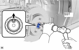
Using SST and a hammer, release the staked part of the front axle shaft nut.
- SST
- 09930-00010
Note
Fully loosen the staked part of the front axle shaft nut, otherwise the threads of the drive shaft may be damaged.
-
While applying the brakes, remove the front axle shaft nut.
-
-
SEPARATE FRONT SPEED SENSOR
-
SEPARATE TIE ROD ASSEMBLY
-
SEPARATE FRONT STABILIZER LINK ASSEMBLY
-
SEPARATE FRONT LOWER NO. 1 SUSPENSION ARM SUB-ASSEMBLY
-
SEPARATE FRONT DRIVE SHAFT ASSEMBLY
-
REMOVE FRONT DRIVE SHAFT ASSEMBLY LH
-
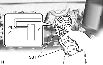
Using SST, remove the front drive shaft assembly LH.
- SST
- 09520-01010
- 09520-24010 ( 09520-32040 )
Note
-
Do not damage the front drive shaft oil seal LH.
-
Do not damage the front axle inboard joint boot.
-
Do not drop the front drive shaft assembly LH.
-
-
REMOVE FRONT DRIVE SHAFT ASSEMBLY RH
-
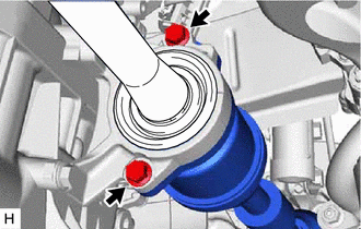
Remove the 2 bolts and pull out the drive shaft together with the drive shaft bearing case sub-assembly.
-
Remove the front drive shaft assembly RH from the drive shaft bearing bracket.
Note
-
Do not damage the front drive shaft oil seal RH.
-
Do not damage the front axle inboard joint boot.
-
Do not drop the front drive shaft assembly RH.
Tech Tips
If it is difficult to disengage the fitting, lightly tap the end of the front drive inboard joint assembly using a brass bar and a hammer.
-
-
-
REMOVE FRONT DRIVE SHAFT HOLE SNAP RING
-
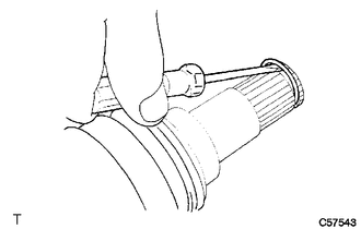
Using a screwdriver, remove the front drive shaft hole snap ring.
-