FLOW SHUTTING VALVE(for Heater) INSTALLATION
PROCEDURE
-
INSTALL FLOW SHUTTING VALVE (WATER BY-PASS HOSE ASSEMBLY)
-
Connect the flow shutting valve (water by-pass hose assembly) to the transmission oil cooler and slide the clip to secure it.
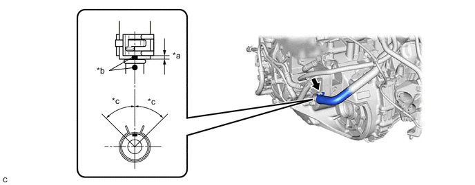
*a 2 to 7 mm (0.0787 to 0.276 in.) *b Paint Mark *c 45° (Tabs of Clip Installation Area) - - Note
-
Make sure to slide the flow shutting valve (water by-pass hose assembly) until it contacts the hose stopper of the transmission oil cooler.
-
Make sure to align the paint mark of the flow shutting valve (water by-pass hose assembly) with the paint mark of the transmission oil cooler.
-
Make sure that the tabs of the clip are within the area shown in the illustration.
-
-
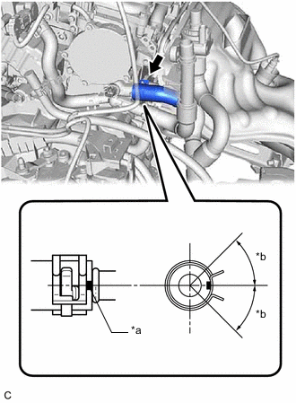
*a Paint Mark *b 45° (Tabs of Clip Installation Area) Connect the flow shutting valve (water by-pass hose assembly) to the water by-pass outlet sub-assembly and slide the clip to secure it.
Note
-
Make sure to slide the flow shutting valve (water by-pass hose assembly) until it contacts the hose stopper of the water by-pass outlet sub-assembly.
-
Make sure that the tabs of the clip are within the area shown in the illustration.
-
-
Install the water hose clamp bracket with the 2 bolts.
- Torque:
- 13 N*m { 133 kgf*cm, 10 ft.*lbf }
-
Engage the 2 clamps to connect the wire harness.
-
Connect the flow shutting valve (water by-pass hose assembly) with the bolt.
- Torque:
- 19 N*m { 194 kgf*cm, 14 ft.*lbf }
-
Connect the No. 2 water by-pass pipe sub-assembly with the bolt.
- Torque:
- 19 N*m { 194 kgf*cm, 14 ft.*lbf }
-
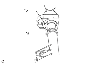
Connect the inlet heater hose connector to the flow shutting valve (water by-pass hose assembly).
Note
Check that there is no damage or foreign matter on the connecting parts of the water lines.
-
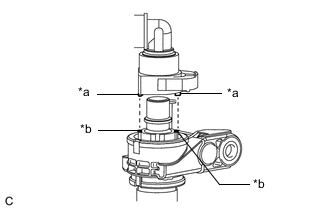
*a Protrusion *b Cutout Align the protrusions of the inlet heater hose connector with the cutouts in the flow shutting valve (water by-pass hose assembly) and push them together until the inlet heater hose connector makes a "click" sound.
-
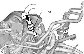
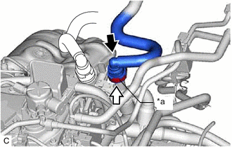
*a Retainer 
Push 
Push in Push in the retainer.
-
Check that the flow shutting valve (water by-pass hose assembly) and inlet heater hose connector are securely connected by pulling on them.
-
-
Connect the outlet heater hose connector to the No. 2 water by-pass pipe sub-assembly.
Note
Check that there is no damage or foreign matter on the connecting parts of the water lines.
-
*a Protrusion *b Cutout Align the protrusion of the No. 2 water by-pass pipe sub-assembly with the cutout in the outlet heater hose connector and push them together until the outlet heater hose connector makes a "click" sound.
-
*a Retainer Push Push in Push in the retainer.
-
Check that the No. 2 water by-pass pipe sub-assembly and outlet heater hose connector are securely connected by pulling on them.
-
-
Engage the clamp to connect the engine wire harness to the water hose clamp bracket.
-
Connect the 3 connectors.
-
Engage the clamp to connect the vacuum hose to the engine wire harness.
-
-
INSTALL FLOW SHUTTING VALVE (NO. 1 WATER BY-PASS HOSE)