FLOW SHUTTING VALVE(for ATF) INSTALLATION
PROCEDURE
-
INSTALL FLOW SHUTTING VALVE (NO. 1 WATER BY-PASS HOSE)
-
Install the flow shutting valve (No. 1 water by-pass hose) with the bolt.
- Torque:
- 19 N*m { 194 kgf*cm, 14 ft.*lbf }
-
Connect the flow shutting valve connector.
-
Connect the flow shutting valve (No. 1 water by-pass hose) to the transmission oil cooler and slide the clip to secure it.
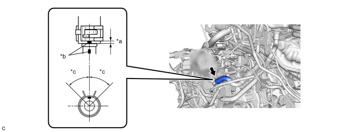
*a 2 to 7 mm (0.0787 to 0.276 in.) *b Paint Mark *c 45° (Tabs of Clip Installation Area) - - Note
-
Make sure to slide the flow shutting valve (No. 1 water by-pass hose) until it contacts the hose stopper of the transmission oil cooler.
-
Make sure to align the paint mark of the flow shutting valve (No. 1 water by-pass hose) with the paint mark of the transmission oil cooler.
-
Make sure that the tabs of the clip are within the area shown in the illustration.
-
-
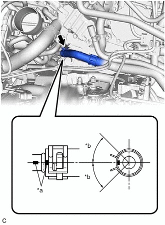
*a Paint Mark *b 45° (Tabs of Clip Installation Area) Connect the flow shutting valve (No. 1 water by-pass hose) to the water outlet and slide the clip to secure it.
Note
-
Make sure to slide the flow shutting valve (No. 1 water by-pass hose until it contacts the hose) stopper of the water outlet.
-
Make sure to align the paint mark of the flow shutting valve (No. 1 water by-pass hose) with the paint mark of the water outlet.
-
Make sure that the tabs of the clip are within the area shown in the illustration.
-
-
Engage the 2 clamps to connect the flow shutting valve (No. 1 water by-pass hose) and transmission breather hose to the hose clamp.
-
Engage the 3 clamps to install the hose clamp.
-
Engage the 3 clamps to install the transmission breather clamp.
-
-
INSTALL BATTERY CLAMP SUB-ASSEMBLY
-
INSTALL BATTERY
-
INSTALL ECM
-
ADD ENGINE COOLANT
-
INSPECT FOR COOLANT LEAK
-
INSTALL FRONT FENDER APRON SEAL LH
-
INSTALL NO. 2 ENGINE UNDER COVER ASSEMBLY
-
INSTALL NO. 1 ENGINE UNDER COVER
-
INSTALL FRONT WHEEL OPENING EXTENSION PAD LH
-
INSTALL FRONT WHEEL OPENING EXTENSION PAD RH
-
INSTALL FRONT WHEEL LH