EXHAUST MANIFOLD INSTALLATION
PROCEDURE
-
INSTALL STUD BOLT
Tech Tips
If a stud bolt is deformed or its threads are damaged, replace it.
-
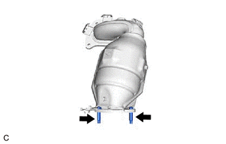
Using an E8 "TORX" socket wrench, install the 2 stud bolts to the exhaust manifold assembly LH (TWC: Front Catalyst).
- Torque:
- 19.5 N*m { 199 kgf*cm, 14 ft.*lbf }
-
-
INSTALL EXHAUST MANIFOLD TO HEAD GASKET (for Bank 2)
-
Install a new exhaust manifold to head gasket (for Bank 2) to the cylinder head sub-assembly.
-
-
INSTALL EXHAUST MANIFOLD ASSEMBLY LH (TWC: Front Catalyst)
-
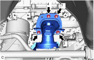
Temporarily install the exhaust manifold assembly LH (TWC: Front Catalyst) with the 4 nuts.
-
Temporarily install the No. 2 manifold stay to the exhaust manifold assembly LH (TWC: Front Catalyst) and cylinder block sub-assembly with the bolt and nut.
-
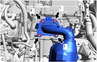
Using a 12 mm deep socket wrench, tighten the 4 nuts in the order shown in the illustration.
- Torque:
- 21 N*m { 214 kgf*cm, 15 ft.*lbf }
-
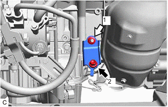

Bolt 
Nut Tighten the bolt and nut in the order shown in the illustration.
- Torque:
- Nut
- 35 N*m { 357 kgf*cm, 26 ft.*lbf }
- Bolt
- 34 N*m { 347 kgf*cm, 25 ft.*lbf }
-
-
CONNECT NO. 5 WATER BY-PASS HOSE
-
Engage the 2 clamps to connect the No. 5 water by-pass hose and No. 6 water by-pass hose to the hose clamp.
-
-
INSTALL NO. 2 EXHAUST MANIFOLD HEAT INSULATOR
-
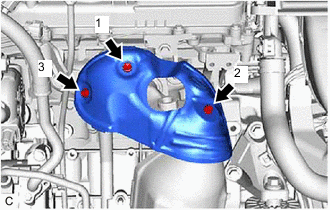
Install the No. 2 exhaust manifold heat insulator to the exhaust manifold assembly LH (TWC: Front Catalyst) with the 3 bolts in the order shown in the illustration.
- Torque:
- 8.5 N*m { 87 kgf*cm, 75 in.*lbf }
-
-
INSTALL ENGINE OIL LEVEL DIPSTICK GUIDE
-
INSTALL AIR FUEL RATIO SENSOR (for Bank 2)
-
INSTALL COOL AIR INTAKE DUCT SEAL
-
INSTALL V-BANK COVER SUB-ASSEMBLY
-
INSTALL EXHAUST MANIFOLD TO HEAD GASKET (for Bank 1)
-
Install a new exhaust manifold to head gasket (for Bank 1) to the cylinder head sub-assembly RH.
-
-
INSTALL EXHAUST MANIFOLD ASSEMBLY RH (TWC: Front Catalyst)
-
Temporarily install the exhaust manifold assembly RH (TWC: Front Catalyst) with the 4 nuts.
-
Using a 12 mm deep socket wrench, tighten the 4 nuts in the order shown in the illustration.
- Torque:
- 21 N*m { 214 kgf*cm, 15 ft.*lbf }
-
-
INSTALL NO. 1 EXHAUST MANIFOLD HEAT INSULATOR
-
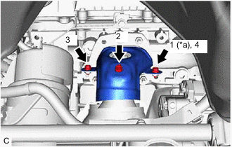
*a Temporarily Tighten Install the No. 1 exhaust manifold heat insulator to the exhaust manifold assembly (TWC: Front Catalyst) with the 3 bolts in the order shown in the illustration.
- Torque:
- 8.5 N*m { 87 kgf*cm, 75 in.*lbf }
-
-
INSTALL AIR FUEL RATIO SENSOR (for Bank 1)
-
INSTALL FRONT EXHAUST PIPE ASSEMBLY (TWC: Rear Catalyst)
-
Install 3 new gaskets to the front exhaust pipe assembly (TWC: Rear Catalyst).
-
Connect the front exhaust pipe assembly (TWC: Rear Catalyst) to the exhaust pipe support.
-
Install the front exhaust pipe assembly (TWC: Rear Catalyst) with 4 new bolts and 4 new nuts.
- Torque:
- 43 N*m { 438 kgf*cm, 32 ft.*lbf }
-
Engage the 2 wire harness clamps.
-
Connect the 2 heated oxygen sensor connectors.
-
-
INSTALL NO. 1 EXHAUST PIPE SUPPORT BRACKET (for Lower Side)
-
INSTALL BODY MOUNTING PLATE
-
INSPECT FOR EXHAUST GAS LEAK
-
INSTALL NO. 1 ENGINE UNDER COVER
-
INSTALL FRONT WHEEL OPENING EXTENSION PAD LH
-
INSTALL FRONT WHEEL OPENING EXTENSION PAD RH