INTAKE MANIFOLD REMOVAL
CAUTION / NOTICE / HINT
The necessary procedures (adjustment, calibration, initialization or registration) that must be performed after parts are removed and installed, or replaced during intake manifold removal/installation are shown below.
| Replaced Part or Performed Procedure | Necessary Procedure | Effect/Inoperative Function when Necessary Procedure not Performed | Link |
|---|---|---|---|
| Battery terminal is disconnected/reconnected | Perform steering sensor zero point calibration | Lane departure alert system (w/ Steering Control) | |
| Pre-collision system | |||
| Memorize steering angle neutral point | Parking assist monitor system | ||
|
Inspection After Repair |
|
PROCEDURE
-
REMOVE COWL TOP VENTILATOR LOUVER SUB-ASSEMBLY
-
REMOVE FRONT CENTER UPPER SUSPENSION BRACE SUB-ASSEMBLY (for LHD)
-
REMOVE FRONT CENTER UPPER SUSPENSION BRACE SUB-ASSEMBLY (for RHD)
-
REMOVE FUEL INJECTOR ASSEMBLY
-
REMOVE THROTTLE WITH MOTOR BODY ASSEMBLY
-
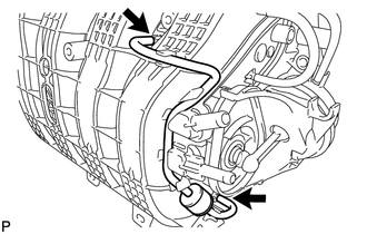
DISCONNECT NO. 2 VENTILATION HOSE
-
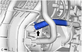
Slide the clip and disconnect the No. 2 ventilation hose from the intake manifold.
-
-
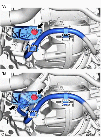
DISCONNECT UNION TO CONNECTOR TUBE HOSE (for LHD)
-
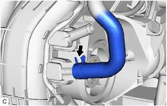
Slide the clip and disconnect the union to connector tube hose from the intake manifold.
-
-
DISCONNECT UNION TO CHECK VALVE HOSE (for RHD)
-
Slide the clip and disconnect the union to check valve hose from the intake manifold.
-
-
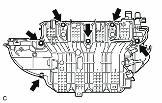
REMOVE INTAKE MANIFOLD
-
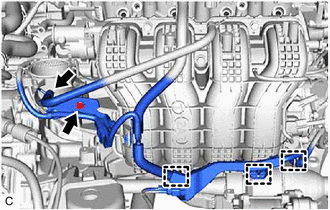
Slide the clip and disconnect the fuel vapor feed hose from the intake manifold.
-
Disengage the 3 wire harness clamps.
-
Remove the bolt and wire harness clamp bracket from the intake manifold.
-
w/ TCV:
-
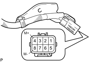
Apply positive (+) battery voltage to terminal 8 (M-) and negative (-) battery voltage to terminal 4 (M+) of the sensor wire connector to close the 4 tumble control valves (TCV).
Note
-
The 4 tumble control valves (TCV) may be damaged if they are not closed before removing the intake manifold.
-
Apply battery voltage for 1 to 3 seconds.
-
If battery voltage is applied for more than 3 seconds, the intake air control valve actuator (for TCV) may be damaged.
-
Do not allow the lead wires to contact the other terminals.
-
-
-
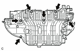
*A w/o TCV *B w/ TCV Remove the bolt and disconnect the engine wire.
-
Disengage the 2 wire harness clamps.
-
w/ TCV:
-
Disconnect the intake air control valve actuator (for TCV) connector.
-
-
w/o TCV:
-
Remove the 6 bolts and intake manifold from the cylinder head sub-assembly.
-
-
w/ TCV:
-
Remove the 6 bolts and intake manifold from the cylinder head sub-assembly.
Note
The 4 tumble control valves (TCV) may be damaged if they are not closed before removing the intake manifold.
Tech Tips
Connect the battery to the terminals of the intake air control valve actuator (for TCV) to operate the motor and close the 4 tumble control valves (TCV).
-
-
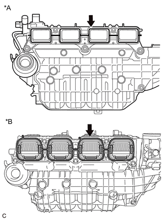
*A w/o TCV *B w/ TCV Remove the intake manifold to head gasket from the intake manifold.
-
Disconnect the 2 vacuum hoses and remove the No. 1 check valve from the intake manifold.
-
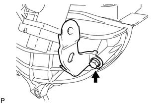
Remove the bolt and wire harness clamp bracket from the intake manifold.
-