FUEL SENDER GAUGE ASSEMBLY REMOVAL
CAUTION / NOTICE / HINT
The necessary procedures (adjustment, calibration, initialization or registration) that must be performed after parts are removed and installed, or replaced during fuel sender gauge assembly removal/installation are shown below.
| Replaced Part or Performed Procedure | Necessary Procedure | Effect/Inoperative Function when Necessary Procedure not Performed | Link |
|---|---|---|---|
| Battery terminal is disconnected/reconnected | Perform steering sensor zero point calibration. | Lane departure alert system (w/ Steering Control) | |
| Pre-collision system | |||
| Memorize steering angle neutral point | Parking assist monitor system |
CAUTION:
-
Never perform work on fuel system components near any possible ignition sources.
-
Vaporized fuel could ignite, resulting in a serious accident.
-

Do not perform work on fuel system components without first disconnecting the cable from the negative (-) battery terminal.
-
Sparks could cause vaporized fuel to ignite, resulting in a serious accident.
PROCEDURE
-
REMOVE FUEL SUCTION TUBE WITH PUMP AND GAUGE ASSEMBLY
-
REMOVE FUEL SENDER GAUGE ASSEMBLY
-
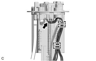
Disconnect the fuel sender gauge assembly connector.
-
Disengage the 2 clamps to disconnect the wire harness from the fuel suction plate sub-assembly.
Note
Do not damage the wire harness.
-

Disengage the claw to remove the fuel sender gauge assembly from the fuel suction tube with pump and gauge assembly.
Note
Be careful not to bend the arm of the fuel sender gauge assembly.
-