FUEL TANK(w/o Canister Pump Module) INSTALLATION
PROCEDURE
-
INSTALL NO. 2 FUEL TANK CUSHION
-
Install 2 new No. 2 fuel tank cushions to the fuel tank assembly.
-
-
INSTALL NO. 6 FUEL TANK CUSHION
-
Install a new No. 6 fuel tank cushion to the fuel tank assembly.
-
-
INSTALL NO. 1 FUEL EVAPORATION TUBE SUB-ASSEMBLY
-
Engage the clamp to install the No. 1 fuel evaporation tube sub-assembly to the fuel tank assembly.
-
-
INSTALL CHARCOAL CANISTER OUTLET HOSE
-
Engage the clamp to install the charcoal canister outlet hose to the fuel tank assembly.
-
-
INSTALL FUEL TANK MAIN TUBE SUB-ASSEMBLY
-
Engage the clamp to install the fuel tank main tube sub-assembly to the fuel tank assembly.
-
-
INSTALL FUEL TANK ASSEMBLY
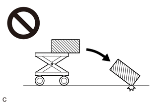
CAUTION:
The fuel tank assembly is very heavy. Be sure to follow the procedure described in the repair manual, or the fuel tank assembly may fall off the engine lifter.
-
Set the fuel tank assembly on an engine lifter.
Note
Using height adjustment attachments and plate lift attachments, keep the fuel tank assembly horizontal.
-
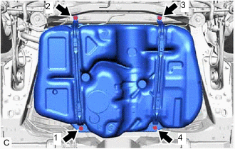
Using the engine lifter, slowly raise the fuel tank assembly, and then install the fuel tank assembly, No. 1 fuel tank band sub-assembly LH and No. 1 fuel tank band sub-assembly RH with the 4 bolts in the order shown in the illustration.
- Torque:
- 45 N*m { 459 kgf*cm, 33 ft.*lbf }
Note
-
Be careful not to drop the fuel tank assembly.
-
When installing the fuel tank assembly, tilt it slightly to prevent it from interfering with the surrounding parts.
-
-
CONNECT FUEL TANK MAIN TUBE SUB-ASSEMBLY
-
Connect the fuel tank main tube sub-assembly to the fuel pipe.
-
-
CONNECT NO. 1 FUEL EVAPORATION TUBE SUB-ASSEMBLY
-
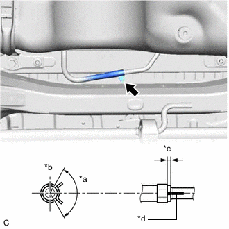
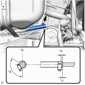
*a 120° *b Up *c 2.0 to 7.0 mm (0.0787 to 0.276 in.) *d Paint Mark Connect the No. 1 fuel evaporation tube sub-assembly to the fuel pipe and slide the clip to secure it.
Tech Tips
Engage the clip within the area shown in the illustration.
-
-
CONNECT FUEL TANK TO FILLER PIPE HOSE
-
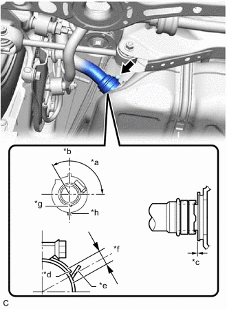
*a 120° *b Up *c 0 to 3.0 mm (0 to 0.118 in.) *d Clamp End *e Stopper *f +/- 2.0 mm (0.0787 in.) *g Paint Mark (Fuel Tank To Filler Pipe Hose) *h Protrusion (Fuel Tank Assembly) Connect the fuel tank to filler pipe hose to the fuel tank assembly and tighten the clamp to secure it.
Tech Tips
-
Make sure the clamp and fuel tank to filler pipe hose are positioned within the area shown in the illustration.
-
Make sure that the clamp end is positioned within 2.0 mm (0.0787 in.) of the stopper.
-
-
-
CONNECT FUEL TANK BREATHER TUBE SUB-ASSEMBLY
-
*a 120° *b Up *c 0 to 3.0 mm (0 to 0.118 in.) *d 2.0 to 7.0 mm (0.0787 to 0.276 in.) Connect the fuel tank breather tube sub-assembly to the fuel tank filler pipe assembly and tighten the clamp to secure it.
Tech Tips
Make sure the clamp and fuel tank breather tube sub-assembly are positioned within the area shown in the illustration.
-
-
CONNECT CHARCOAL CANISTER OUTLET HOSE
-
Connect the charcoal canister outlet hose to the fuel tank filler pipe assembly.
-
-
INSTALL NO. 1 FUEL TANK PROTECTOR
-
Install the No. 1 fuel tank protector to the fuel tank assembly with the 4 clips.
-
-
INSTALL CENTER EXHAUST PIPE ASSEMBLY
-
INSTALL FUEL SUCTION TUBE WITH PUMP AND GAUGE ASSEMBLY
-
ADD FUEL