CAUTION / NOTICE / HINT
The necessary procedures (adjustment, calibration, initialization or registration) that must be performed after parts are removed and installed, or replaced during port fuel injector assembly removal/installation are shown below.
| Replaced Part or Performed Procedure | Necessary Procedure | Effect/Inoperative Function when Necessary Procedure not Performed | Link |
|---|---|---|---|
| Battery terminal is disconnected/reconnected | Perform steering sensor zero point calibration | Lane departure alert system (w/ Steering Control) | |
| Pre-collision system | |||
| Memorize steering angle neutral point | Parking assist monitor system | ||
|
Inspection after repair |
|
Click herefor A25A-FKS (w/ Canister Pump Module) Click herefor A25A-FKS (w/o Canister Pump Module) |
-
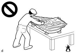
Never perform work on fuel system components near any possible ignition sources.
-
Vaporized fuel could ignite, resulting in a serious accident.
-

Do not perform work on fuel system components without first disconnecting the cable from the negative (-) battery terminal.
-
Sparks could cause vaporized fuel to ignite, resulting in a serious accident.
This procedure includes the removal of small-head bolts. Refer to Small-Head Bolts of Basic Repair Hint to identify the small-head bolts.
PROCEDURE
- Click here
PRECAUTION
Note:After turning the ignition switch off, waiting time may be required before disconnecting the cable from the negative (-) battery terminal. Therefore, make sure to read the disconnecting the cable from the negative (-) battery terminal notices before proceeding with work.
- Click here
DISCHARGE FUEL SYSTEM PRESSURE
- Click here
DISCONNECT CABLE FROM NEGATIVE BATTERY TERMINAL
Note:When disconnecting the cable, some systems need to be initialized after the cable is reconnected.
- Click here
REMOVE INTAKE MANIFOLD
- Click here
REMOVE NO. 1 FUEL PIPE SUB-ASSEMBLY
- Click here
DISCONNECT FUEL TUBE SUB-ASSEMBLY
-
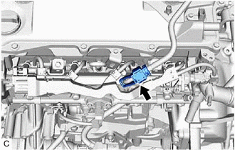
Remove the fuel pipe clamp from the fuel tube connector.
-
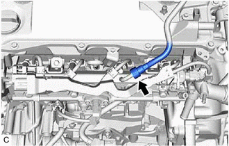
Disconnect the fuel tube sub-assembly from the fuel delivery pipe with sensor assembly.
-
- Click here
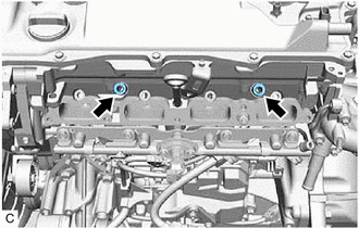
REMOVE FUEL DELIVERY PIPE WITH SENSOR ASSEMBLY
-
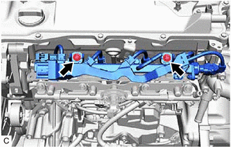
Remove the 2 bolts and fuel delivery pipe with sensor assembly with the 4 port fuel injector assemblies from the cylinder head sub-assembly.
Note:Be careful not to drop the port fuel injector assemblies when removing the fuel delivery pipe with sensor assembly.
-
- Click here
REMOVE NO. 1 DELIVERY PIPE SPACER
-
Remove the 2 No. 1 delivery pipe spacers from the cylinder head sub-assembly.
-
- Click here
REMOVE INJECTOR VIBRATION INSULATOR
-
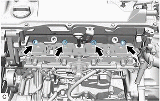
Remove the 4 injector vibration insulators from the cylinder head sub-assembly.
-
- Click here
REMOVE NO. 5 ENGINE WIRE
-
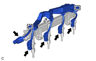
Disconnect the 4 port fuel injector assembly connectors and fuel pressure sensor connector.
-
Disengage the 2 clamps to remove the No. 5 engine wire from the fuel delivery pipe with sensor assembly.
-
- Click here
REMOVE PORT FUEL INJECTOR ASSEMBLY
-
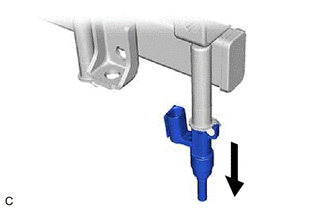
Pull the 4 port fuel injector assemblies out of the fuel delivery pipe with sensor assembly.
-
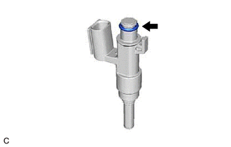
Remove the O-ring from each port fuel injector assembly.
-
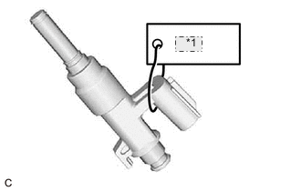
Table 2. *1 No. 1 Attach a tag or label with the corresponding cylinder number to each port fuel injector assembly so that they can be installed to their original locations.
Note:Cover the port fuel injector assemblies with plastic bags to prevent damage and contamination.
-