FUEL INJECTOR INSTALLATION

PROCEDURE
-
INSTALL FUEL INJECTOR ASSEMBLY
-
Apply a light coat of gasoline or spindle oil to new O-rings, and then install one to each fuel injector assembly.
-
Apply a light coat of gasoline or spindle oil where the fuel delivery pipe contacts each O-ring.
-
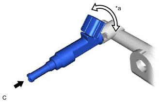
*a Turn 
Push While turning the fuel injector assembly left and right, install it to the fuel delivery pipe.
Note
-
Do not damage the fuel injector assembly or O-ring.
-
Make sure that the O-ring is not twisted or moved out of place when installing the fuel injector assembly.
-
After installing each fuel injector assembly, check that it turns smoothly. If not, replace the O-ring with a new one.
Tech Tips
Use the same procedure to install the other fuel injector assemblies.
-
-
-
INSTALL INJECTOR VIBRATION INSULATOR
-
Install 4 new injector vibration insulators to the cylinder head sub-assembly.
-
-
INSTALL FUEL DELIVERY SPACER
-
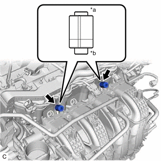
*a Fuel Delivery Pipe Side *b Cylinder Head Sub-assembly Side Install the 2 No. 1 fuel delivery spacers to the cylinder head sub-assembly.
Note
Install the No. 1 delivery pipe spacers in the correct direction.
-
-
INSTALL FUEL DELIVERY PIPE
-
Install the fuel delivery pipe with the 4 fuel injector assemblies with the 2 bolts.
- Torque:
- 21 N*m { 214 kgf*cm, 15 ft.*lbf }
Note
-
Be careful not to drop the fuel injector assemblies when installing the fuel delivery pipe.
-
Check that the fuel injector assemblies turn smoothly after installing the fuel delivery pipe.
-
-
CONNECT ENGINE WIRE
-
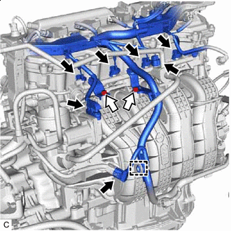

Bolt Engage the clamp to connect the engine wire.
-
Install the 2 wire harness brackets to the intake manifold with the 2 bolts.
- Torque:
- 10 N*m { 102 kgf*cm, 7 ft.*lbf }
-
Connect the 4 fuel injector assembly connectors, throttle body with motor assembly connector, purge valve (purge VSV) connector and sensor wire connector.
-
-
INSTALL VACUUM SWITCHING VALVE ASSEMBLY (for ACIS)
-
CONNECT FUEL TUBE SUB-ASSEMBLY
-
Connect the fuel tube sub-assembly to the fuel pipe.
-
Install the No. 1 fuel pipe clamp to the fuel tube connector and close the cover of the No. 1 fuel pipe clamp.
-
Engage the clamp to connect the fuel tube sub-assembly to the fuel hose clamp.
-
-
INSTALL AIR CLEANER CAP WITH AIR CLEANER HOSE
-
INSTALL NO. 1 ENGINE COVER SUB-ASSEMBLY
-
CONNECT CABLE TO NEGATIVE BATTERY TERMINAL
Note
When disconnecting the cable, some systems need to be initialized after the cable is reconnected.
-
INSPECT FOR FUEL LEAK
-
PERFORM INITIALIZATION
-
Perform "Inspection After Repair" after replacing a fuel injector assembly.
-