FUEL INJECTOR REMOVAL

CAUTION / NOTICE / HINT
The necessary procedures (adjustment, calibration, initialization or registration) that must be performed after parts are removed and installed, or replaced during fuel injector assembly removal/installation are shown below.
| Replaced Part or Performed Procedure | Necessary Procedure | Effect/Inoperative Function when Necessary Procedure not Performed | Link |
|---|---|---|---|
| Battery terminal is disconnected/reconnected | Perform steering sensor zero point calibration | Lane departure alert system (w/ Steering Control) | |
| Pre-collision system | |||
| Memorize steering angle neutral point | Parking assist monitor system | ||
| Replacement of fuel injector assembly | Inspection after repair |
|
CAUTION:
-
Never perform work on fuel system components near any possible ignition sources.
-
Vaporized fuel could ignite, resulting in a serious accident.
-

Do not perform work on fuel system components without first disconnecting the cable from the negative (-) battery terminal.
-
Sparks could cause vaporized fuel to ignite, resulting in a serious accident.
PROCEDURE
-
PRECAUTION
Note
After turning the ignition switch off, waiting time may be required before disconnecting the cable from the negative (-) battery terminal. Therefore, make sure to read the disconnecting the cable from the negative (-) battery terminal notices before proceeding with work.
-
DISCHARGE FUEL SYSTEM PRESSURE
-
DISCONNECT CABLE FROM NEGATIVE BATTERY TERMINAL
Note
When disconnecting the cable, some systems need to be initialized after the cable is reconnected.
-
REMOVE NO. 1 ENGINE COVER SUB-ASSEMBLY
-
REMOVE AIR CLEANER CAP WITH AIR CLEANER HOSE
-
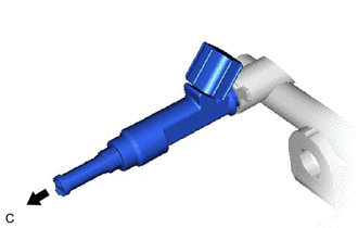
DISCONNECT FUEL TUBE SUB-ASSEMBLY
-
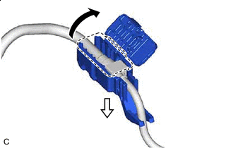

Open 
Pull Open the cover of the No. 1 fuel pipe clamp and remove the No. 1 fuel pipe clamp from the fuel tube connector.
-
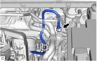
Disconnect the fuel tube sub-assembly from the fuel pipe.
-
Disengage the clamp to disconnect the fuel tube sub-assembly from the fuel hose clamp.
-
-
REMOVE VACUUM SWITCHING VALVE ASSEMBLY (for ACIS)
-
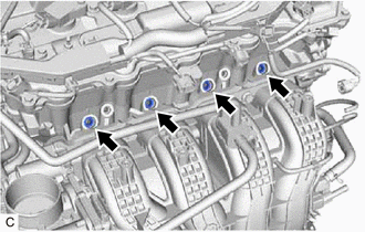
DISCONNECT ENGINE WIRE
-
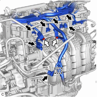
Bolt Disconnect the 4 fuel injector assembly connectors, throttle body with motor assembly connector, purge valve (purge VSV) connector and sensor wire connector.
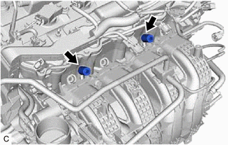
-
Remove the 2 bolts and separate the 2 wire harness brackets from the intake manifold.
-
Disengage the clamp to disconnect the engine wire.
-
-
REMOVE FUEL DELIVERY PIPE
-
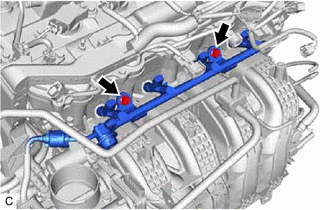
Remove the 2 bolts and fuel delivery pipe with the 4 fuel injector assemblies.
Note
Be careful not to drop the fuel injector assemblies when removing the fuel delivery pipe.
-
-
REMOVE FUEL DELIVERY SPACER
-
Remove the 2 No. 1 fuel delivery spacers from the cylinder head sub-assembly.
-
-
REMOVE INJECTOR VIBRATION INSULATOR
-
Remove the 4 injector vibration insulators from the cylinder head sub-assembly.
-
-
REMOVE FUEL INJECTOR ASSEMBLY
-
Pull the 4 fuel injector assemblies out of the fuel delivery pipe.
-
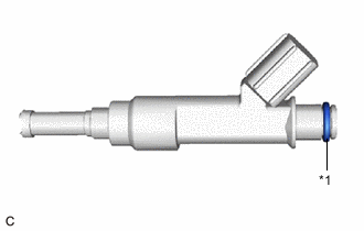
*1 O-ring Remove the O-ring from each fuel injector assembly.
-
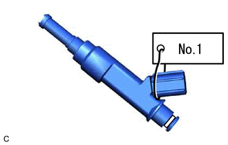
Attach a tag or label with the corresponding cylinder number to each fuel injector assembly so that they can be installed to their original locations.
Note
Cover the fuel injector assemblies with plastic bags to prevent damage and contamination.
-