PROCEDURE
- Click here
INSTALL NO. 1 OIL NOZZLE SUB-ASSEMBLY
-
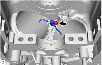
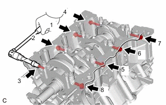
Using a 5 mm hexagon socket wrench, install the 3 No. 1 oil nozzle sub-assemblies to the cylinder block sub-assembly with the 3 bolts.
9.0 N*m 92 kgf*cm 80 in.*lbf
-
- Click here
INSTALL PISTON
Tip:Perform this procedure only when replacement of the piston pin hole snap ring (rear side) is necessary.
-
Using a screwdriver, install a new piston pin hole snap ring (rear side) at one end of the piston pin hole.
-
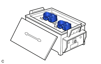
Gradually heat the piston to approximately 80°C (176°F).
-
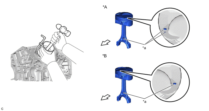
Coat the piston pin with engine oil.
CAUTION:Be sure to wear protective gloves.
-
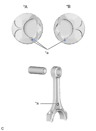
*A for Bank 1 *B for Bank 2 *a Front Mark Align the front marks of the piston and connecting rod sub-assembly, and push in the piston pin with your thumb.
Tip:The piston and piston pin are a matched set.
-
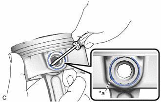
*a Cutout Using a screwdriver, install a new piston pin hole snap ring at the other end of the piston pin hole.
Note:Make sure that the end gap of the piston pin hole snap ring is not aligned with the cutout of the piston pin hole.
-
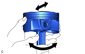
Check the fitting condition between the piston and piston pin.
-
Move the connecting rod back and forth on the piston pin. Check the fitting condition.
Tip:If abnormal movement is felt, replace the piston and piston pin as a set.
-
Rotate the piston back and forth on the piston pin. Check the fitting condition.
Tip:
-
If abnormal movement is felt, replace the piston and piston pin as a set.
-
Perform Inspection After Repair after replacing the piston.
-
-
-
- Click here
INSTALL PISTON RING SET
-
Install the oil ring expander and 2 side rails by hand.
-
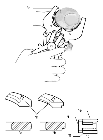
*a No. 1 Compression Ring *b No. 2 Compression Ring *c Oil Ring *d Piston Ring Expander *e Upper Side Rail *f Oil Ring Expander *g Lower Side Rail *h Code Mark Using a piston ring expander, install the No. 1 compression ring and No. 2 compression ring as shown in the illustration.
Note:
-
Install the No. 1 compression ring with the code mark (T1) facing upward.
-
Install the No. 2 compression ring with the code mark (T2) facing upward.
-
-
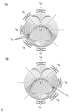
*A for Bank 1 *B for Bank 2 *a No. 1 Compression Ring *b No. 2 Compression Ring *c Front Mark *d Lower Side Rail *e Oil Ring Expander *f Upper Side Rail Position the piston ring set so that the ring ends are as shown in the illustration.
Note:Do not align the ring ends.
-
- Click here
INSTALL CRANKSHAFT BEARING
-
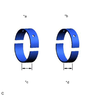
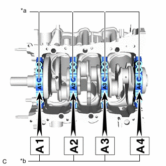
*a No. 1 and No. 4 Crankshaft Bearing *b No. 2 and No. 3 Crankshaft Bearing *c 20.9 mm *d 17.9 mm Clean the main journals and both surfaces of the crankshaft bearings.
Note:Crankshaft bearings come in widths of 17.9 mm (0.705 in.) and 20.9 mm (0.823 in.). Install the 20.9 mm (0.823 in.) crankshaft bearings to the No. 1 and No. 4 cylinder block journal positions. Install the 17.9 mm (0.705 in.) crankshaft bearings to the No. 2 and No. 3 positions.
-
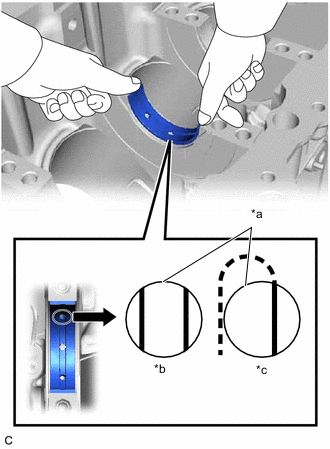
*a Upper Crankshaft Bearing *b Correct *c Incorrect Install the upper crankshaft bearings.
-
Install the upper crankshaft bearings to the cylinder block sub-assembly as shown in the illustration.
Note:
-
Do not apply engine oil to the crankshaft bearings or the contact surfaces.
-
Both sides of the oil groove in the cylinder block sub-assembly should be visible through the oil feed holes in the crankshaft bearing. The amount visible on each side of the holes should be equal.
-
Do not allow coolant to come into contact with the crankshaft bearing inner surface.
-
If any coolant comes into contact with the crankshaft bearing inner surface, replace the crankshaft bearing with a new one.
-
-
-
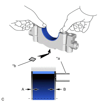
*a Vernier Caliper *b Number Mark Install the lower crankshaft bearings.
-
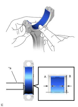
Install the lower crankshaft bearings to the crankshaft bearing caps.
-
Using a vernier caliper, measure the distance between the crankshaft bearing cap edge and lower crankshaft bearing edge.
Difference Between (A) and (B) 0.7 mm (0.0276 in.) or less Note:
-
Do not apply engine oil to the crankshaft bearings or the contact surfaces.
-
Do not allow coolant to come into contact with the crankshaft bearing inner surface.
-
If any coolant comes into contact with the crankshaft bearing inner surface, replace the crankshaft bearing with a new one.
-
-
-
- Click here
INSTALL CRANKSHAFT THRUST WASHER SET
-
Apply engine oil to the crankshaft thrust washer set.
-
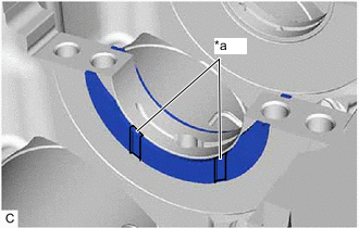
*a Oil Groove Install the crankshaft thrust washer set under the No. 2 journal position of the cylinder block sub-assembly with the oil grooves facing outward.
-
- Click here
INSTALL CRANKSHAFT
-
Apply engine oil to the crankshaft bearings, then place the crankshaft on the cylinder block sub-assembly.
-
*a Projection *b Number Mark Confirm the projections and numbers of the crankshaft bearing caps and install the 4 crankshaft bearing caps to the cylinder block sub-assembly.
Tip:A number is marked on each crankshaft bearing cap to indicate its installation position.
-
Apply a light coat of engine oil to the threads and under the heads of the crankshaft bearing cap set bolts.
-
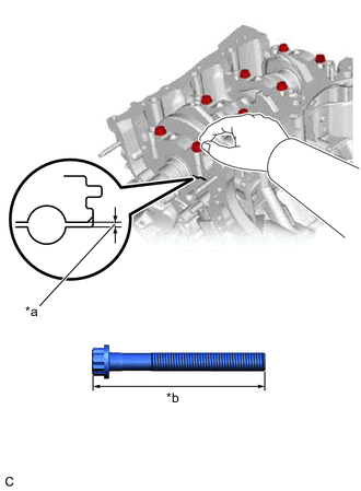
*a Less than 6 mm *b Bolt Length Temporarily install the 8 crankshaft bearing cap set bolts to the inside positions.
Bolt Length 100 to 102 mm (3.94 to 4.02 in.) -
Push the crankshaft bearing cap with your hand until the clearance between the crankshaft bearing cap and the cylinder block sub-assembly is less than 6 mm (0.236 in.) by using the 2 inside crankshaft bearing cap set bolts as a guide.
-
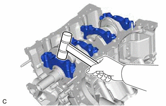
Using a plastic hammer, lightly tap the crankshaft bearing cap to ensure a proper fit.
-
Apply a light coat of engine oil to the threads and under the heads of the 8 crankshaft bearing cap set bolts.
-
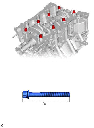
*a Bolt Length Temporarily install the 8 crankshaft bearing cap set bolts to the outside positions.
Bolt Length 105.5 to 107.5 mm (4.15 to 4.23 in.) -
Install the crankshaft bearing cap set bolts.
Tip:The crankshaft bearing cap set bolts are tightened in 2 progressive steps.
-
Step 1:
-
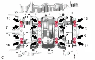
Uniformly tighten the 16 crankshaft bearing cap set bolts in several steps in the order shown in the illustration.
61 N*m 622 kgf*cm 45 ft.*lbf Tip:If a crankshaft bearing cap bolt cannot be tightened to the specified torque, replace it.
-
-
Step 2:
-
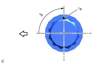
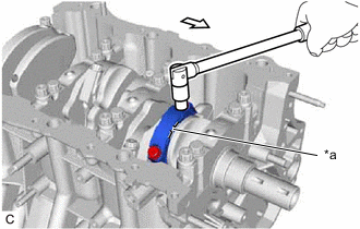
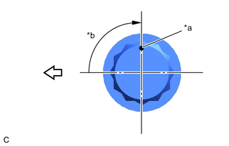
*a Paint Mark *b Turn 90° 
Front of Engine Mark the front of the crankshaft bearing cap set bolts with paint.
-
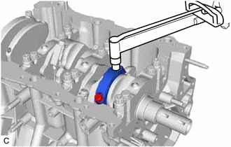
Tighten the crankshaft bearing cap set bolts 90° in the order shown in the illustration.
-
Check that the paint marks are now at a 90° angle to the front.
-
-
Install 8 new seal washers and uniformly tighten the 8 crankshaft bearing cap set bolts in several steps in the order shown in the illustration.
51.5 N*m 525 kgf*cm 38 ft.*lbf -
Check that the crankshaft turns smoothly.
-
Check the crankshaft thrust clearance.
-
- Click here
INSTALL CONNECTING ROD BEARING
-
Install the connecting rod bearings to the connecting rod sub-assembly and connecting rod cap.
-
*a Vernier Caliper Using a vernier caliper, measure the distance between the connecting rod sub-assembly, connecting rod cap edges and the connecting rod bearing edge.
Difference Between (A) and (B) 0.7 mm (0.0276 in.) or less Note:Do not apply engine oil to the connecting rod bearings or the contact surfaces.
-
- Click here
INSTALL PISTON SUB-ASSEMBLY WITH CONNECTING ROD
-
Apply engine oil to the cylinder walls, the pistons, and the surfaces of the connecting rod bearings.
-
*A for Bank 1 *B for Bank 2 *a No. 1 Compression Ring *b No. 2 Compression Ring *c Front Mark *d Lower Side Rail *e Oil Ring Expander *f Upper Side Rail Position the piston ring set so that the ring ends are as shown in the illustration.
Note:Do not align the ring ends.
-
*A for Bank 1 *B for Bank 2 *a Front Mark - - Front of Engine - - Using a piston ring compressor, push the piston and connecting rod sub-assembly into the cylinder with the front mark of the piston facing the front of the engine.
Note:Match the connecting rod cap with the connecting rod sub-assembly.
-
*a Front Mark Front of Engine Check that the front mark of the connecting rod cap is facing the front of the engine.
-
Apply a light coat of engine oil to the threads and under the heads of the connecting rod bolts.
-
Install the 2 connecting rod bolts.
Tip:The connecting rod bolts are tightened in 2 progressive steps.
-
Step 1:
-
Alternately tighten the 2 connecting rod bolts in several steps.
24.5 N*m 250 kgf*cm 18 ft.*lbf
-
-
*a Paint Mark *b Turn 90° Front of Engine Step 2:
-
Mark the front of each connecting rod bolt with paint.
-
Further tighten the connecting rod bolts 90° as shown in the illustration.
-
Check that the paint marks are now at a 90° angle to the front.
-
-
Confirm that the crankshaft turns smoothly.
-
Check the connecting rod thrust clearance.
-
- Click here
INSTALL CYLINDER BLOCK WATER JACKET SPACER
-
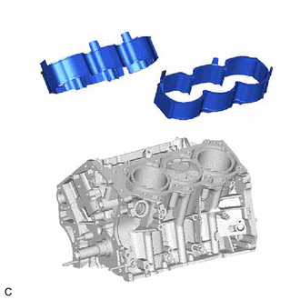
Install the cylinder block water jacket spacer and cylinder block water jacket spacer LH to the cylinder block sub-assembly.
Note:Firmly press the cylinder block water jacket spacer into the cylinder block sub-assembly and confirm that it is not protruding from the surface.
-