CYLINDER BLOCK REPLACEMENT

PROCEDURE
-
REPLACE STRAIGHT PIN
Note
If a straight pin is deformed, replace it.
-
Using a plastic hammer, tap in new straight pins to the cylinder block sub-assembly.
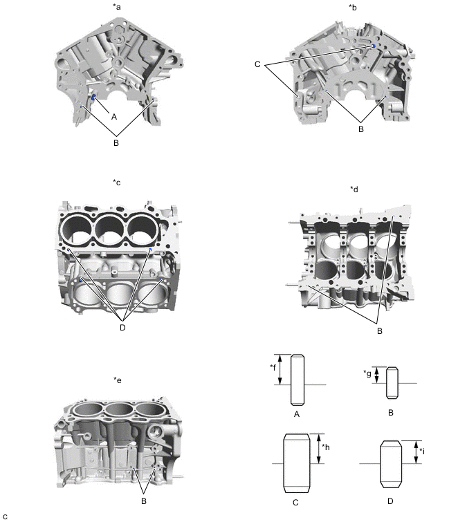
*a Front Side *b Rear Side *c Top Side *d Bottom Side *e RH Side *f 23 mm (0.906 in.) *g 6 mm (0.236 in.) *h 11 mm (0.433 in.) *i 9 mm (0.354 in.) - - Standard Protrusion Height Item Specified Condition Pin (A) 23 mm (0.906 in.) Pin (B) 6 mm (0.236 in.) Pin (C) 11 mm (0.433 in.) Pin (D) 9 mm (0.354 in.)
-
-
REPLACE STUD BOLT
Note
If a stud bolt is deformed or its threads are damaged, replace it.
-
Using E8 and E10 "TORX" socket wrenches, install the stud bolts to the cylinder block sub-assembly.
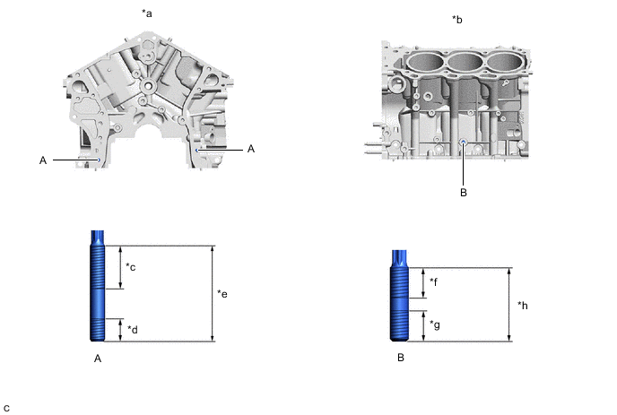
*a Front Side *b LH Side *c 24 mm (0.9449 in.) *d 12 mm (0.4724 in.) *e 52 mm (2.05 in.) *f 23 mm (0.906 in.) *g 15 mm (0.591 in.) *h 40 mm (1.57 in.) - Torque:
- 10 N*m { 102 kgf*cm, 7 ft.*lbf }
-
-
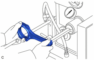
REPLACE CONNECTING ROD SMALL END BUSH
-
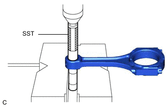
Using SST and a press, press out the connecting rod small end bush.
- SST
- 09222-30010
-
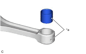
*a Oil Hole Align the oil hole of a new connecting rod small end bush with the oil hole of the connecting rod.
-
Using SST and a press, push in the connecting rod small end bush.
- SST
- 09222-30010
-
Using a pin hole grinder, hone the connecting rod small end bush to obtain the standard oil clearance between the connecting rod small end bush and piston pin.
Standard Oil Clearance 0.005 to 0.011 mm (0.000197 to 0.000433 in.) -
Coat the piston pin with engine oil, and push it into the connecting rod with your thumb.
Tech Tips
Check that the piston pin fits at a normal room temperature.
-