CYLINDER HEAD REPLACEMENT

PROCEDURE
-
REPLACE INTAKE VALVE GUIDE BUSH
-
Heat the cylinder head sub-assembly to between 80 and 100°C (176 to 212°F).
-
Place the cylinder head sub-assembly on wooden blocks.
CAUTION:
Be sure to wear protective gloves.
-
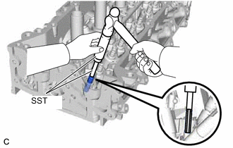
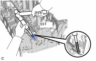
Using SST and a hammer, tap out the intake valve guide bush.
- SST
- 09201-01055
- 09950-70010 ( 09951-07100 )
-
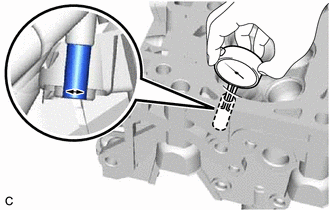
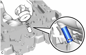
Using a caliper gauge, measure the intake valve guide bush bore diameter of the cylinder head sub-assembly.
Standard Intake Valve Guide Bush Bore Diameter 10.285 to 10.306 mm (0.405 to 0.406 in.) New Guide Bush Selection Chart Bush Size Specified Condition STD 10.333 to 10.344 mm (0.40681 to 0.40724 in.) O/S 0.05 10.383 to 10.394 mm (0.40877 to 0.40921 in.) Standard Bush Length 41.3 to 41.7 mm (1.63 to 1.64 in.) Tech Tips
-
If the intake valve guide bush bore diameter of the cylinder head sub-assembly is more than 10.306 mm (0.406 in.), machine the intake valve guide bush bore of the cylinder head sub-assembly to a dimension of 10.335 to 10.356 mm (0.407 to 0.408 in.) to install an O/S 0.05 intake valve guide bush.
-
If the intake valve guide bush bore diameter of the cylinder head sub-assembly is more than 10.356 mm (0.408 in.), replace the cylinder head sub-assembly.
-
-
Heat the cylinder head sub-assembly to between 80 and 100°C (176 to 212°F).
-
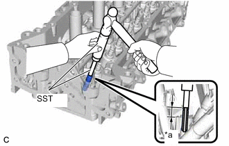
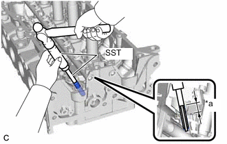
*a Protrusion Height Using SST and a hammer, tap in the selected intake valve guide bush.
- SST
- 09201-10000 ( 09201-01050 )
- 09950-70010 ( 09951-07100 )
Standard Protrusion Height 17.75 to 17.95 mm (0.699 to 0.707 in.) -
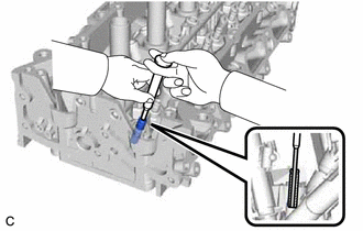
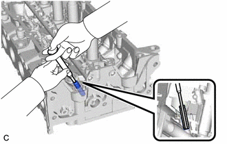
Using a sharp 5.5 mm reamer, ream the intake valve guide bush to obtain the standard oil clearance.
Standard Oil Clearance 0.025 to 0.060 mm (0.000984 to 0.00236 in.)
-
-
REPLACE EXHAUST VALVE GUIDE BUSH
-
Heat the cylinder head sub-assembly to between 80 and 100°C (176 to 212°F).
-
Place the cylinder head sub-assembly on wooden blocks.
CAUTION:
Be sure to wear protective gloves.
-
Using SST and a hammer, tap out the exhaust valve guide bush.
- SST
- 09201-01055
- 09950-70010 ( 09951-07100 )
-
Using a caliper gauge, measure the exhaust valve guide bush bore diameter of the cylinder head sub-assembly.
Standard Exhaust Valve Guide Bush Bore Diameter 10.285 to 10.306 mm (0.405 to 0.406 in.) New Guide Bush Selection Chart Bush Size Specified Condition STD 10.333 to 10.344 mm (0.40681 to 0.40724 in.) O/S 0.05 10.383 to 10.394 mm (0.40877 to 0.40921 in.) Standard Bush Length 43.3 to 43.7 mm (1.70 to 1.72 in.) Tech Tips
-
If the exhaust valve guide bush bore diameter of the cylinder head sub-assembly is more than 10.306 mm (0.406 in.), machine the exhaust valve guide bush bore of the cylinder head sub-assembly to a dimension of 10.335 to 10.356 mm (0.407 to 0.408 in.) to install an O/S 0.05 exhaust valve guide bush.
-
If the exhaust valve guide bush bore diameter of the cylinder head sub-assembly is more than 10.356 mm (0.408 in.), replace the cylinder head sub-assembly.
-
-
Heat the cylinder head sub-assembly to between 80 and 100°C (176 to 212°F).
-
*a Protrusion Height Using SST and a hammer, tap in the selected exhaust valve guide bush.
- SST
- 09201-10000 ( 09201-01050 )
- 09950-70010 ( 09951-07100 )
Standard Protrusion Height 17.75 to 17.95 mm (0.699 to 0.707 in.) -
Using a sharp 5.5 mm reamer, ream the exhaust valve guide bush to obtain the standard oil clearance.
Standard Oil Clearance 0.030 to 0.065 mm (0.00118 to 0.00256 in.)
-
-
REPLACE RING PIN
Note
It is not necessary to remove the ring pins unless they are being replaced.
-
Remove the 2 ring pins.
-
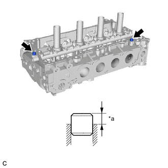
*a Protrusion Height Using a plastic hammer, tap in 2 new ring pins to the cylinder head sub-assembly.
Standard Protrusion Height 6.5 to 7.5 mm (0.256 to 0.295 in.)
-