CAMSHAFT INSTALLATION
CAUTION / NOTICE / HINT
Note
This procedure includes the installation of small-head bolts. Refer to Small-Head Bolts of Basic Repair Hint to identify the small-head bolts.
PROCEDURE
-
INSTALL NO. 2 CAMSHAFT
Tech Tips
Perform inspection after repair after replacing the No. 2 camshaft.
-
w/ Canister Pump Module:
-
w/o Canister Pump Module:
-
Clean the camshaft journals and camshaft housing sub-assembly.
-
Apply a light coat of engine oil to the camshaft journals and camshaft housing sub-assembly.
-
Install the No. 2 camshaft to the camshaft housing sub-assembly.
-
-
INSTALL CAMSHAFT
Tech Tips
Perform inspection after repair after replacing the camshaft.
-
w/ Canister Pump Module:
-
w/o Canister Pump Module:
-
Clean the camshaft journals, camshaft housing sub-assembly and camshaft bearing caps.
-
Apply a light coat of engine oil to the camshaft journals, camshaft housing sub-assembly and camshaft bearing caps.
-
Install the camshaft to the camshaft housing sub-assembly.
-
-
INSTALL CAMSHAFT BEARING CAP
-
INSTALL CAMSHAFT HOUSING SUB-ASSEMBLY
-
INSTALL FUEL PUMP LIFTER GUIDE
-
INSTALL TIMING CHAIN COVER ASSEMBLY
-
Clean the contact surfaces of the timing chain cover assembly, cylinder head sub-assembly, camshaft housing sub-assembly, cylinder block sub-assembly and stiffening crankcase assembly, and confirm that no oil, moisture, or other foreign matter is on the surfaces.
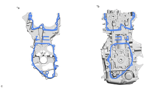
*a Timing Chain Cover Assembly Side *b Engine Assembly Side -
Apply seal packing in a continuous line to the timing chain cover assembly as shown in the illustration.
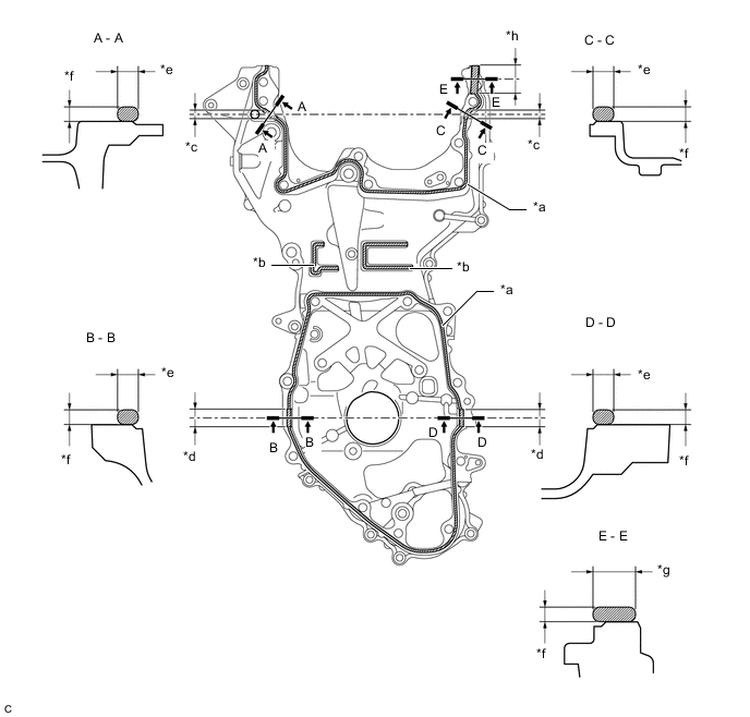
*a 2.5 to 3.5 mm (0.0984 to 0.138 in.) *b 2.0 to 6.0 mm (0.0787 to 0.236 in.) *c 10 mm (0.394 in.) *d 20 mm (0.787 in.) *e 4.0 to 6.0 mm (0.157 to 0.236 in.) *f 3.0 to 4.0 mm (0.118 to 0.157 in.) *g 8.0 to 10 mm (0.315 to 0.394 in.) *h 30 mm (1.18 in.) 
Seal Packing - - Seal Packing Toyota Genuine Seal Packing Black, Three Bond 1207B or equivalent Note
-
Clean the surfaces with non-residue solvent before applying seal packing.
-
Install the timing chain cover assembly within 3 minutes and tighten the bolts within 10 minutes of applying seal packing.
-
Do not add oil for at least 2 hours after installation.
-
Do not start the engine for at least 2 hours after installation.
-
Make sure that the diameter at the start and end of each line of seal packing is 5 +/- 2 mm (0.197 +/- 0.0787 in.).
-
-
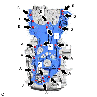
Temporarily install the timing chain cover assembly with the 19 bolts.
Bolt Length Bolt Length (A) 30 mm (1.18 in.) (B) 45 mm (1.77 in.) Note
Make sure there is no oil on the bolts. If oil is found on any bolt, clean it before installation.
-
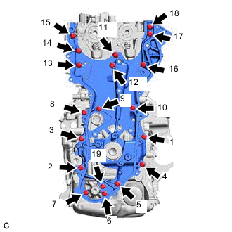
Tighten the 19 bolts in the order shown in the illustration.
- Torque:
- 27 N*m { 275 kgf*cm, 20 ft.*lbf }
-
-
INSTALL CAMSHAFT TIMING GEAR ASSEMBLY
-
INSTALL CAMSHAFT TIMING EXHAUST GEAR ASSEMBLY
-
SET NO. 1 CYLINDER TO TDC (COMPRESSION)
-
INSTALL NO. 1 CHAIN VIBRATION DAMPER
-
INSTALL CHAIN SUB-ASSEMBLY
-
INSTALL CHAIN TENSIONER SLIPPER
-
INSTALL NO. 1 CHAIN TENSIONER ASSEMBLY
-
INSTALL OIL PUMP DRIVE CHAIN SUB-ASSEMBLY
-
SET NO. 1 CYLINDER TO TDC (COMPRESSION)
-
INSTALL NO. 2 TIMING GEAR COVER ASSEMBLY
-
INSTALL TIMING CHAIN COVER OIL SEAL
-
INSTALL SPARK PLUG TUBE GASKET
-
INSTALL CYLINDER HEAD COVER SUB-ASSEMBLY
-
INSTALL CRANKSHAFT PULLEY ASSEMBLY
-
INSTALL VACUUM PUMP ASSEMBLY
-
INSTALL CAM TIMING CONTROL MOTOR O-RING
-
INSTALL CAM TIMING CONTROL MOTOR WITH EDU ASSEMBLY
-
INSTALL CAM TIMING OIL CONTROL SOLENOID ASSEMBLY
-
INSTALL OIL PRESSURE CONTROL VALVE ASSEMBLY
-
INSTALL ENGINE OIL LEVEL DIPSTICK GUIDE
-
INSTALL IGNITION COIL ASSEMBLY
-
TEMPORARILY INSTALL FUEL PUMP ASSEMBLY (for High Pressure)
-
TEMPORARILY INSTALL NO. 1 FUEL PIPE SUB-ASSEMBLY
-
INSTALL FUEL PUMP ASSEMBLY (for High Pressure)
-
INSTALL NO. 1 FUEL PIPE SUB-ASSEMBLY
-
CONNECT FUEL TUBE SUB-ASSEMBLY
-
INSTALL NO. 1 INTAKE MANIFOLD TO HEAD GASKET
-
INSTALL INTAKE MANIFOLD
-
INSTALL NO. 2 WATER BY-PASS PIPE
-
INSTALL NO. 3 WATER BY-PASS PIPE
-
INSTALL EGR VALVE ASSEMBLY
-
INSTALL WATER HOSE CONNECTOR
-
INSTALL NO. 1 EGR PIPE SUB-ASSEMBLY
-
INSTALL NO. 1 EGR COOLER BRACKET
-
INSTALL EGR COOLER ASSEMBLY
-
INSTALL THROTTLE BODY GASKET
-
INSTALL THROTTLE BODY WITH MOTOR ASSEMBLY
-
INSTALL EXHAUST MANIFOLD (TWC: Front Catalyst)
-
INSTALL MANIFOLD STAY
-
INSTALL NO. 1 EXHAUST MANIFOLD HEAT INSULATOR
-
INSTALL NO. 3 TIMING CHAIN COVER
-
INSTALL TIMING GEAR COVER INSULATOR
-
INSTALL V-RIBBED BELT TENSIONER ASSEMBLY
-
INSTALL NO. 2 ENGINE COVER
-
INSTALL V-RIBBED BELT
-
INSTALL ENGINE HANGERS
-
REMOVE ENGINE ASSEMBLY FROM ENGINE STAND