CAMSHAFT REMOVAL
CAUTION / NOTICE / HINT
The necessary procedures (adjustment, calibration, initialization, or registration) that must be performed after parts are removed and installed, or replaced during camshaft removal/installation are shown below.
| Replaced Part or Performed Procedure | Necessary Procedure | Effect/Inoperative Function when Necessary Procedure not Performed | Link |
|---|---|---|---|
| Battery terminal is disconnected/reconnected | Perform steering sensor zero point calibration | Lane departure alert system (w/ Steering Control) | |
| Pre-collision system | |||
| Memorize steering angle neutral point | Parking assist monitor system | ||
| Replacement of ECM | Vehicle Identification Number (VIN) registration | MIL comes on | w/ Canister Pump Module: Click here w/o Canister Pump Module: Click here |
| Perform code registration (Immobiliser system) | Engine start function | See Service Bulletin for the registration method. | |
|
Inspection After Repair |
|
w/ Canister Pump Module: Click here w/o Canister Pump Module: Click here |
| Replacement of automatic transaxle assembly |
|
|
Click here for UB80E Initialization Click here for UB80E Registration |
| Replacement of ECM (If possible, read the transaxle compensation code from the previous ECM) |
|
||
| Replacement of ECM (If impossible, read the transaxle compensation code from the previous ECM) |
|
||
| Replacement of ECM | Perform code registration (Immobiliser function) |
|
See Service Bulletin for the registration method. |
| Suspension, tires, etc. (The vehicle height changes because of suspension or tire replacement) |
Rear television camera assembly optical axis (Back camera position setting) | Parking assist monitor system | Click here for Initialization Click here for Calibration |
| Perform headlight ECU sub-assembly LH initialization | Lighting system (EXT) (w/ Automatic Headlight Beam Level Control System) | ||
| Front wheel alignment adjustment | Perform system variant learning and acceleration sensor zero point calibration. |
|
Note
This procedure includes the removal of small-head bolts. Refer to Small-Head Bolts of Basic Repair Hint to identify the small-head bolts.
PROCEDURE
-
INSTALL ENGINE ASSEMBLY TO ENGINE STAND
-
REMOVE ENGINE HANGERS
-
REMOVE V-RIBBED BELT
-
REMOVE NO. 2 ENGINE COVER
-
REMOVE V-RIBBED BELT TENSIONER ASSEMBLY
-
REMOVE TIMING GEAR COVER INSULATOR
-
REMOVE NO. 3 TIMING CHAIN COVER
-
REMOVE NO. 1 EXHAUST MANIFOLD HEAT INSULATOR
-
REMOVE MANIFOLD STAY
-
REMOVE EXHAUST MANIFOLD (TWC: Front Catalyst)
-
REMOVE THROTTLE BODY WITH MOTOR ASSEMBLY
-
REMOVE THROTTLE BODY GASKET
-
REMOVE EGR COOLER ASSEMBLY
-
REMOVE NO. 1 EGR COOLER BRACKET
-
REMOVE NO. 1 EGR PIPE SUB-ASSEMBLY
-
REMOVE WATER HOSE CONNECTOR
-
REMOVE EGR VALVE ASSEMBLY
-
REMOVE NO. 3 WATER BY-PASS PIPE
-
REMOVE NO. 2 WATER BY-PASS PIPE
-
REMOVE INTAKE MANIFOLD
-
REMOVE NO. 1 INTAKE MANIFOLD TO HEAD GASKET
-
DISCONNECT FUEL TUBE SUB-ASSEMBLY
-
REMOVE NO. 1 FUEL PIPE SUB-ASSEMBLY
-
REMOVE FUEL PUMP ASSEMBLY (for High Pressure)
-
REMOVE IGNITION COIL ASSEMBLY
-
REMOVE ENGINE OIL LEVEL DIPSTICK GUIDE
-
REMOVE OIL PRESSURE CONTROL VALVE ASSEMBLY
-
REMOVE CAMSHAFT POSITION SENSOR (for Intake Side)
-
REMOVE CAMSHAFT POSITION SENSOR (for Exhaust Side)
-
REMOVE CAM TIMING OIL CONTROL SOLENOID ASSEMBLY
-
REMOVE CAM TIMING CONTROL MOTOR WITH EDU ASSEMBLY
-
REMOVE CAM TIMING CONTROL MOTOR O-RING
-
REMOVE VACUUM PUMP ASSEMBLY
-
REMOVE CRANKSHAFT PULLEY ASSEMBLY
-
REMOVE CYLINDER HEAD COVER SUB-ASSEMBLY
-
REMOVE SPARK PLUG TUBE GASKET
-
REMOVE ENGINE MOUNTING BRACKET RH
-
REMOVE NO. 2 TIMING GEAR COVER ASSEMBLY
-
REMOVE TIMING CHAIN COVER OIL SEAL
-
SET NO. 1 CYLINDER TO TDC (COMPRESSION)
-
REMOVE OIL PUMP DRIVE CHAIN SUB-ASSEMBLY
-
REMOVE NO. 1 CHAIN TENSIONER ASSEMBLY
-
REMOVE CHAIN TENSIONER SLIPPER
-
REMOVE CHAIN SUB-ASSEMBLY
-
REMOVE NO. 1 CHAIN VIBRATION DAMPER
-
REMOVE CAMSHAFT TIMING EXHAUST GEAR ASSEMBLY
-
REMOVE CAMSHAFT TIMING GEAR ASSEMBLY
-
REMOVE TIMING CHAIN COVER ASSEMBLY
-
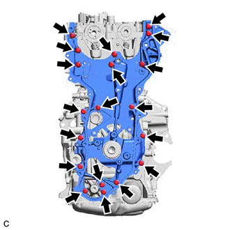
Remove the 19 bolts and timing chain cover assembly from the camshaft housing sub-assembly, cylinder head sub-assembly, cylinder block sub-assembly, stiffening crankcase assembly and oil pump assembly.
-
Remove the timing chain cover assembly by prying between the cylinder head sub-assembly, camshaft housing sub-assembly, cylinder block sub-assembly and stiffening crankcase assembly with a screwdriver with its tip wrapped with protective tape.
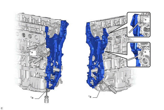
*a Protective Tape - - Note
Be careful not to damage the contact surfaces of the cylinder head sub-assembly, camshaft housing sub-assembly, cylinder block sub-assembly, stiffening crankcase assembly and timing chain cover assembly.
-
-
REMOVE FUEL PUMP LIFTER GUIDE
-
REMOVE CAMSHAFT HOUSING SUB-ASSEMBLY
-
REMOVE CAMSHAFT BEARING CAP
-
REMOVE CAMSHAFT
-
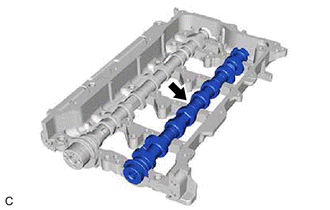
Remove the camshaft from the camshaft housing sub-assembly.
-
-
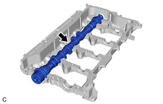
REMOVE NO. 2 CAMSHAFT
-
Remove the No. 2 camshaft from the camshaft housing sub-assembly.
-