PROCEDURE
- Click here
INSTALL IGNITION COIL ASSEMBLY
- Click here
INSTALL ENGINE COOLANT TEMPERATURE SENSOR
- Click here
INSTALL ENGINE OIL PRESSURE SWITCH ASSEMBLY
- Click here
INSTALL KNOCK CONTROL SENSOR
- Click here
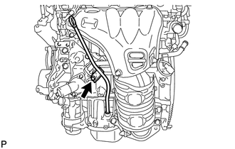
INSTALL SENSOR WIRE
-
Install the sensor wire to the cylinder block sub-assembly with the bolt.
21 N*m 214 kgf*cm 15 ft.*lbf -
Connect the knock control sensor connector.
-
- Click here
INSTALL INTAKE MANIFOLD
- Click here
INSTALL FUEL INJECTOR ASSEMBLY
- Click here
INSTALL INJECTOR VIBRATION INSULATOR
- Click here
INSTALL FUEL DELIVERY SPACER
- Click here
INSTALL FUEL DELIVERY PIPE
- Click here
CONNECT NO. 2 VENTILATION HOSE
- Click here
INSTALL VACUUM SWITCHING VALVE ASSEMBLY (for ACIS)
- Click here
INSTALL WATER BY-PASS HOSE
-
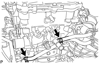
Install the No. 1 water by-pass hose to the cylinder head sub-assembly and slide the clip to secure it.
-
Install the No. 2 water by-pass hose to the No. 1 water by-pass pipe and slide the clip to secure it.
-
- Click here
INSTALL THROTTLE BODY GASKET
- Click here
INSTALL THROTTLE BODY WITH MOTOR ASSEMBLY
- Click here
INSTALL NO. 1 COMPRESSOR MOUNTING BRACKET
-
Install the No. 1 compressor mounting bracket with the 4 bolts.
21 N*m 214 kgf*cm 15 ft.*lbf
-
- Click here
INSTALL DRIVE SHAFT BEARING BRACKET
-
Install the drive shaft bearing bracket with the 3 bolts.
63.7 N*m 650 kgf*cm 47 ft.*lbf Note:Make sure that the bolts and bolt holes are free of oil. Clean them if necessary.
-
- Click here
INSTALL COMPRESSOR ASSEMBLY WITH PULLEY
-
for Type A:
-
Using an E8 "TORX" socket wrench, temporarily install the compressor assembly with pulley with the 2 stud bolts.
10 N*m 102 kgf*cm 7 ft.*lbf -
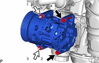

Bolt 
Nut Install the compressor assembly with pulley with the 2 bolts and 2 nuts.
24.5 N*m 250 kgf*cm 18 ft.*lbf Tip:Tighten the bolts and nuts in the order shown in the illustration to install the compressor assembly with pulley.
-
-
for Type B:
-
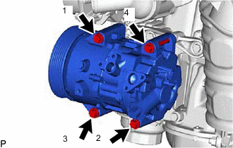
Install the compressor assembly with pulley with the 4 bolts.
24.5 N*m 250 kgf*cm 18 ft.*lbf Tip:Tighten the bolts in the order shown in the illustration to install the compressor assembly with pulley.
-
-
- Click here
INSTALL WIRE HARNESS CLAMP BRACKET
-
Install the wire harness clamp bracket with the bolt.
10 N*m 102 kgf*cm 7 ft.*lbf -
Install the wire harness clamp bracket with the bolt.
10 N*m 102 kgf*cm 7 ft.*lbf -
Install the wire harness clamp bracket with the nut.
10 N*m 102 kgf*cm 7 ft.*lbf
-
- Click here
INSTALL GENERATOR ASSEMBLY
- Click here
INSTALL V-RIBBED BELT
- Click here
INSTALL EXHAUST MANIFOLD CONVERTER SUB-ASSEMBLY
- Click here
INSTALL NO. 1 EXHAUST MANIFOLD HEAT INSULATOR
- Click here
INSTALL NO. 2 MANIFOLD STAY
- Click here
INSTALL MANIFOLD STAY
- Click here
INSTALL ENGINE OIL LEVEL DIPSTICK GUIDE
-
Apply a light coat of engine oil to a new O-ring.
-
Install the O-ring to the engine oil level dipstick guide.
-
Install the engine oil level dipstick guide with the bolt.
10 N*m 102 kgf*cm 7 ft.*lbf -
Install the engine oil level dipstick.
-