CAMSHAFT POSITION SENSOR REMOVAL
CAUTION / NOTICE / HINT
The necessary procedures (adjustment, calibration, initialization or registration) that must be performed after parts are removed and installed, or replaced during VVT sensor removal/installation are shown below.
| Replaced Part or Performed Procedure | Necessary Procedure | Effect/Inoperative Function when Necessary Procedure not Performed | Link |
|---|---|---|---|
|
Inspection after repair |
|
PROCEDURE
-
REMOVE INTAKE AIR SURGE TANK ASSEMBLY
-
REMOVE VVT SENSOR (for Intake Side of Bank 1)
-
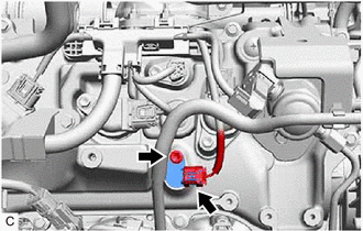
Disconnect the VVT sensor connector.
-
Remove the bolt and VVT sensor from the cylinder head cover sub-assembly.
Note
If the VVT sensor has been struck or dropped, replace it.
-
-
REMOVE VVT SENSOR (for Exhaust Side of Bank 1)
-
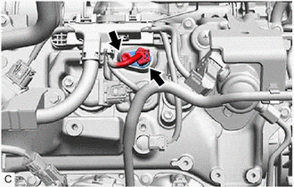
Disconnect the VVT sensor connector.
-
Remove the bolt and VVT sensor from the cylinder head cover sub-assembly.
Note
If the VVT sensor has been struck or dropped, replace it.
-
-
REMOVE VVT SENSOR (for Intake Side of Bank 2)
-
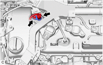
Disconnect the VVT sensor connector.
-
Remove the bolt and VVT sensor from the cylinder head cover sub-assembly LH.
Note
If the VVT sensor has been struck or dropped, replace it.
-
-
REMOVE VVT SENSOR (for Exhaust Side of Bank 2)
-
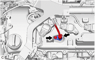
Disconnect the VVT sensor connector.
-
Remove the bolt and VVT sensor from the cylinder head cover sub-assembly LH.
Note
If the VVT sensor has been struck or dropped, replace it.
-