SFI SYSTEM, Diagnostic DTC:P012015
| DTC Code | DTC Name |
|---|---|
| P012015 | Throttle / Pedal Position Sensor / Switch "A" Circuit Short to Battery or Open |
DESCRIPTION
Refer to DTC P012011.
| DTC No. | Detection Item | DTC Detection Condition | Trouble Area | MIL | Memory | Note |
|---|---|---|---|---|---|---|
| P012015 | Throttle / Pedal Position Sensor / Switch "A" Circuit Short to Battery or Open | The output voltage of VTA1 is higher than 4.535 V for 2 seconds or more (1 trip detection logic). |
|
Comes on | DTC stored | SAE Code: P0123 |
MONITOR DESCRIPTION
The ECM uses the throttle position sensor to monitor the throttle valve opening angle. If the VTA1 terminal voltage is higher than the threshold, the ECM will illuminate the MIL and store this DTC.
MONITOR STRATEGY
| Frequency of Operation | Continuous |
CONFIRMATION DRIVING PATTERN
-
Connect the GTS to the DLC3.
-
Turn the engine switch on (IG).
-
Turn the GTS on.
-
Clear the DTCs (even if no DTCs are stored, perform the clear DTC procedure).
-
Turn the engine switch off and wait for at least 30 seconds.
-
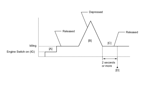
Turn the engine switch on (IG) [A].
-
Turn the GTS on.
-
Start the engine.
-
With the vehicle stationary, fully depress and release the accelerator pedal [B].
-
Idle the engine for 2 seconds or more [C].
-
Enter the following menus: Powertrain / Engine / Trouble Codes [D].
-
Read the pending DTCs.
Tech Tips
-
If a pending DTC is output, the system is malfunctioning.
-
If a pending DTC is not output, perform the following procedure.
-
-
Enter the following menus: Powertrain / Engine / Utility / All Readiness.
-
Input the DTC: P012015.
-
Check the DTC judgment result.
GTS Display Description NORMAL
-
DTC judgment completed
-
System normal
ABNORMAL
-
DTC judgment completed
-
System abnormal
INCOMPLETE
-
DTC judgment not completed
-
Perform driving pattern after confirming DTC enabling conditions
Tech Tips
-
If the judgment result is NORMAL, the system is normal.
-
If the judgment result is ABNORMAL, the system is malfunctioning.
-
If the judgment result is INCOMPLETE, perform steps [B] through [D] again.
-
FAIL-SAFE
When this DTC is stored, the ECM enters fail-safe mode. During fail-safe mode, the ECM cuts the current to the throttle actuator, and the throttle valve is returned to a 7° throttle valve opening angle by the return spring. The ECM then adjusts the engine output by controlling the fuel injection (intermittent fuel-cut) and ignition timing, in accordance with the accelerator pedal angle, to allow the vehicle to continue running at a minimal speed. If the accelerator pedal is depressed firmly and gently, the vehicle can be driven slowly.
Fail-safe mode continues until a pass condition is detected, and the engine switch is turned off.
CAUTION / NOTICE / HINT
Tech Tips
Read Freeze Frame Data using the GTS. The ECM records vehicle and driving condition information as Freeze Frame Data the moment a DTC is stored. When troubleshooting, Freeze Frame Data can help determine if the vehicle was moving or stationary, if the engine was warmed up or not, if the air fuel ratio was lean or rich, and other data from the time the malfunction occurred.
PROCEDURE
-
CHECK HARNESS AND CONNECTOR (THROTTLE POSITION SENSOR - ECM)
-
Disconnect the throttle body with motor assembly connector.
-
Disconnect the ECM connector.
-
Measure the resistance according to the value(s) in the table below.
Standard Resistance Tester Connection Condition Specified Condition C82-6 (VTA) - C96-122 (VTA1) Always Below 1 Ω C82-3 (E2) - C96-120 (ETA) Always Below 1 Ω C82-5 (VC) or C96-121 (VCTA) - Body ground and other terminals Always 10 kΩ or higher C82-6 (VTA) or C96-122 (VTA1) - Body ground and other terminals Always 10 kΩ or higher Result Proceed to OK NG
NG 
REPAIR OR REPLACE HARNESS OR CONNECTOR
OK 
-
-
CHECK TERMINAL VOLTAGE (POWER SOURCE OF THROTTLE POSITION SENSOR)
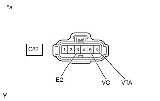
*a Front view of wire harness connector
(to Throttle Body with Motor Assembly)
-
Disconnect the throttle body with motor assembly connector.
-
Turn the engine switch on (IG).
-
Measure the voltage according to the value(s) in the table below.
Standard Voltage Tester Connection Condition Specified Condition C82-5 (VC) - C82-3 (E2) Engine switch on (IG) 4.5 to 5.5 V C82-6 (VTA) - C82-3 (E2) Engine switch on (IG) 3.0 to 5.0 V Result Proceed to OK NG
NG
REPLACE ECM Click here
OK
-
-
CHECK HARNESS AND CONNECTOR (RESISTANCE OF ECM)
-
Disconnect the throttle body with motor assembly connector.
-
Measure the resistance according to the value(s) in the table below.
Standard Resistance Tester Connection Condition Specified Condition C82-5 (VC) - C82-6 (VTA) Engine switch off 190 to 210 kΩ Result Proceed to OK NG
NG
REPLACE ECM Click here
OK
-
-
READ VALUE USING GTS (THROTTLE POSITION SENSOR NO.1 VOLTAGE)
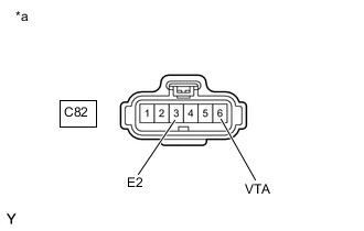
*a Front view of wire harness connector
(to Throttle Body with Motor Assembly)
-
Disconnect the throttle body with motor assembly connector.
-
Connect the GTS to the DLC3.
-
Turn the engine switch on (IG).
-
Turn the GTS on.
-
Enter the following menus: Powertrain / Engine / Data List / Throttle Position Sensor No.1 Voltage.
Powertrain > Engine > Data ListTester Display Throttle Position Sensor No.1 Voltage -
According to the display on the GTS, read the Data List.
Tech Tips
Use the snapshot function to record the value displayed or make a note of it.
-
Turn the engine switch off.
-
Turn the GTS off.
-
Connect terminals 3 (E2) and 6 (VTA) of the throttle body with motor assembly connector on the wire harness side.
Note
If the VTA terminal voltage or the resistance between VTA and E2 is abnormal and terminals 6 (VTA) and 3 (E2) of the throttle body with motor assembly connector are connected, excessive current may flow through the circuit. In this case, do not connect the terminals.
-
Turn the engine switch on (IG).
-
Turn the GTS on.
-
Enter the following menus: Powertrain / Engine / Data List / Throttle Position Sensor No.1 Voltage.
Powertrain > Engine > Data ListTester Display Throttle Position Sensor No.1 Voltage -
Compare the vehicle of the Data List item Throttle Position Sensor No.1 Voltage after the circuit is shorted to the value when the throttle body with motor assembly connector was connected.
Result Result Proceed to Changes from higher than 4.535 V to less than 0.56 V A Does not change from higher than 4.535 V B Tech Tips
Perform "Inspection After Repair" after replacing the throttle body with motor assembly.
A
REPLACE THROTTLE BODY WITH MOTOR ASSEMBLY Click here
B
REPLACE ECM Click here
-