SFI SYSTEM(w/o Canister Pump Module), Diagnostic DTC:P26CA12
| DTC Code | DTC Name |
|---|---|
| P26CA12 | Engine Coolant Pump Circuit Short to Battery |
DESCRIPTION
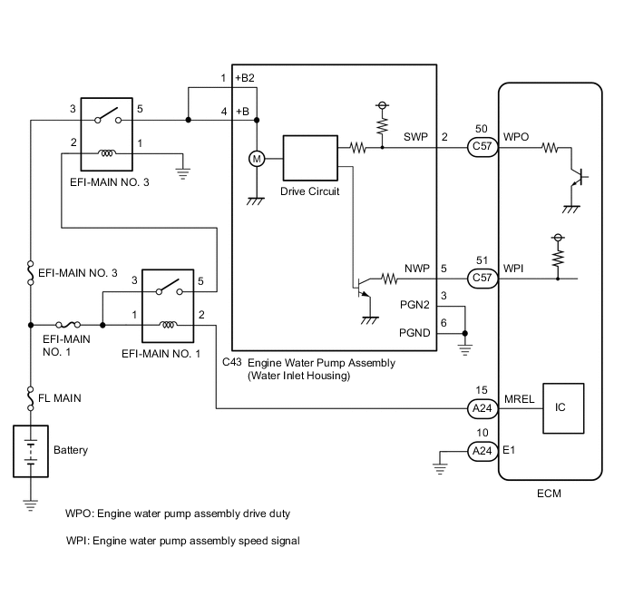
The ECM calculates the necessary cooling amount based on the engine coolant temperature, engine speed and vehicle speed, and controls the engine water pump assembly accordingly. The engine water pump assembly controls the speed of the engine water pump assembly steplessly and optimally based on a duty cycle signal sent by the ECM, which reduces engine warm-up time, improves fuel efficiency and reduces cooling loss.
| DTC No. | Detection Item | DTC Detection Condition | Trouble Area | MIL | Memory | Note |
|---|---|---|---|---|---|---|
| P26CA12 | Engine Coolant Pump Circuit Short to Battery | The operation duty ratio signal (WPO) of the engine water pump assembly is a certain value or more when the engine water pump assembly operation signal is being output (1 trip detection logic). |
|
Comes on | DTC stored | SAE Code: P26CD |
| DTC No. | Data List |
|---|---|
| P26CA12 |
|
MONITOR DESCRIPTION
The ECM outputs an operation duty signal (WPO) to steplessly control the speed of the engine water pump assembly. The ECM outputs an operation duty signal (WPO) to the engine water pump assembly and monitors the actual duty signal (WPO) being output. When the actual operation duty signal (WPO) exceeds a certain value when outputting an operation duty signal (WPO) to the engine water pump assembly, the ECM detects a malfunction and stores a DTC.
MONITOR STRATEGY
| Required Sensors/Components | Engine water pump assembly |
| Frequency of Operation | Continuous |
CONFIRMATION DRIVING PATTERN
-
Connect the GTS to the DLC3.
-
Turn the ignition switch to ON.
-
Turn the GTS on.
-
Clear the DTCs (even if no DTCs are stored, perform the clear DTC procedure).
-
Turn the ignition switch off and wait for at least 30 seconds.
-
Turn the ignition switch to ON [A].
-
Turn the GTS on.
-
Move the shift lever to P [B].
-
Start the engine and maintain the engine speed at 2500 rpm or more for at least 40 seconds [C].
-
Enter the following menus: Powertrain / Engine / Trouble Codes [D].
-
Read the pending DTCs.
Tech Tips
-
If a pending DTC is output, the system is malfunctioning.
-
If a pending DTC is not output, perform the following procedure.
-
-
Enter the following menus: Powertrain / Engine / Utility / All Readiness.
-
Input the DTC: P26CA12.
-
Check the DTC judgment result.
GTS Display Description NORMAL
-
DTC judgment completed
-
System normal
ABNORMAL
-
DTC judgment completed
-
System abnormal
INCOMPLETE
-
DTC judgment not completed
-
Perform driving pattern after confirming DTC enabling conditions
Tech Tips
-
If the judgment result is NORMAL, the system is normal.
-
If the judgment result is ABNORMAL, the system has a malfunction.
-
If the judgment result is INCOMPLETE, perform steps [B] through [D] again.
-
WIRING DIAGRAM
CAUTION / NOTICE / HINT
Tech Tips
Read Freeze Frame Data using the GTS. The ECM records vehicle and driving condition information as Freeze Frame Data the moment a DTC is stored. When troubleshooting, Freeze Frame Data can help determine if the vehicle was moving or stationary, if the engine was warmed up or not, if the air fuel ratio was lean or rich, and other data from the time the malfunction occurred.
PROCEDURE
-
CHECK TERMINAL VOLTAGE (POWER SOURCE OF ENGINE WATER PUMP ASSEMBLY (WATER INLET HOUSING))
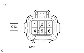
*a Front view of wire harness connector
(to Engine Water Pump Assembly (Water Inlet Housing))
-
Disconnect the engine water pump assembly (water inlet housing) connector.
-
Turn the ignition switch to ON.
-
Measure the voltage according to the value(s) in the table below.
Standard Voltage Tester Connection Condition Specified Condition C43-2 (SWP) - Body ground Ignition switch ON Below 1 V Result Proceed to OK NG
NG 
CHECK HARNESS AND CONNECTOR (ENGINE WATER PUMP ASSEMBLY (WATER INLET HOUSING) - ECM) Click here
OK 
-
-
INSPECT ECM (INTERNAL CIRCUIT)
*a Front view of wire harness connector
(to Engine Water Pump Assembly (Water Inlet Housing))
-
Disconnect the engine water pump assembly (water inlet housing) connector.
-
Turn the ignition switch to ON.
-
Measure the resistance according to the value(s) in the table below.
Standard Tester Connection Condition Specified Condition C43-2 (SWP) - Body ground Ignition switch ON Resistance fluctuates* Tech Tips
-
*: When the connector of the engine water pump assembly is disconnected, the ECM will enter fail-safe mode. In this case, duty control of the transistors in the ECM will be performed and resistance fluctuates.
-
If the resistance fluctuates while the ECM is in fail-safe mode after the connector of the engine water pump assembly is disconnected, it can be determined that the transistor is operating.
-
If the transistor does not operate, the ECM may be malfunctioning.
-
If the resistance fluctuates after turning the ignition switch ON, it can be determined that the ECM is in fail-safe mode.
Result Proceed to OK NG -
OK 
REPLACE ENGINE WATER PUMP ASSEMBLY (WATER INLET HOUSING) Click here
NG
REPLACE ECM Click here
-
-
CHECK HARNESS AND CONNECTOR (ENGINE WATER PUMP ASSEMBLY (WATER INLET HOUSING) - ECM)
-
Disconnect the engine water pump assembly (water inlet housing) connector.
-
Disconnect the ECM connector.
-
Measure the resistance according to the value(s) in the table below.
Standard Resistance Tester Connection Condition Specified Condition C43-2 (SWP) or C57-50 (WPO) - Other terminals Always 10 kΩ or higher Result Proceed to OK NG
OK
REPLACE ECM Click here
NG
REPAIR OR REPLACE HARNESS OR CONNECTOR
-