SFI SYSTEM(w/o Canister Pump Module), Diagnostic DTC:P223711, P223712, P223714, P223716, P22371A, P225111, P225112
| DTC Code | DTC Name |
|---|---|
| P223711 | O2 Sensor Positive Current Control Bank 1 Sensor 1 Circuit Short to Ground |
| P223712 | O2 Sensor Positive Current Control Bank 1 Sensor 1 Circuit Short to Battery |
| P223714 | O2 Sensor Positive Current Control Bank 1 Sensor 1 Circuit Short to Ground or Open |
| P223716 | O2 Sensor Positive Current Control Bank 1 Sensor 1 Circuit Voltage Below Threshold |
| P22371A | O2 Sensor Positive Current Control Bank 1 Sensor 1 Circuit Resistance Below Threshold |
| P225111 | O2 Sensor Negative Current Control Bank 1 Sensor 1 Circuit Short to Ground |
| P225112 | O2 Sensor Negative Current Control Bank 1 Sensor 1 Circuit Short to Battery |
DESCRIPTION
Refer to DTC P003012.
Tech Tips
Although the DTC titles say O2 sensor, these DTCs relate to the air fuel ratio sensor (sensor 1).
| DTC No. | Detection Item | DTC Detection Condition | Trouble Area | MIL | Memory | Note |
|---|---|---|---|---|---|---|
| P223711 | O2 Sensor Positive Current Control Bank 1 Sensor 1 Circuit Short to Ground | The A1A+ voltage is 1.26 V or less for 5 seconds or more (2 trip detection logic). |
|
Comes on | DTC stored | SAE Code: P2238 |
| P223712 | O2 Sensor Positive Current Control Bank 1 Sensor 1 Circuit Short to Battery | The A1A+ voltage is higher than 4.47 V for 5 seconds or more (2 trip detection logic). |
|
Comes on | DTC stored | SAE Code: P2239 |
| P223714 | O2 Sensor Positive Current Control Bank 1 Sensor 1 Circuit Short to Ground or Open | An open or ground short in the circuit between terminals A1A+ and A1A- of the air fuel ratio sensor (sensor 1) while the engine is running (2 trip detection logic). |
|
Comes on | DTC stored | SAE Code: P2237 |
| P223716 | O2 Sensor Positive Current Control Bank 1 Sensor 1 Circuit Voltage Below Threshold | Difference between terminals A1A+ and A1A- is 0.2 V or less for 5 seconds or more (2 trip detection logic). |
|
Comes on | DTC stored | SAE Code: P2238 |
| P22371A | O2 Sensor Positive Current Control Bank 1 Sensor 1 Circuit Resistance Below Threshold | The air fuel ratio sensor (sensor 1) impedance is higher than 185.209 Ω (2 trip detection logic). |
|
Comes on | DTC stored | SAE Code: P2238 |
| P225111 | O2 Sensor Negative Current Control Bank 1 Sensor 1 Circuit Short to Ground | The A1A- voltage is 1.07 V or less for 5 seconds or more (2 trip detection logic). |
|
Comes on | DTC stored | SAE Code: P2252 |
| P225112 | O2 Sensor Negative Current Control Bank 1 Sensor 1 Circuit Short to Battery | The A1A- voltage is higher than 3.93 V for 5 seconds or more (2 trip detection logic). |
|
Comes on | DTC stored | SAE Code: P2253 |
MONITOR DESCRIPTION
These DTCs are stored when there is an open or short in the air fuel ratio sensor (sensor 1) circuit, or the air fuel ratio sensor (sensor 1) output value is abnormal. The voltage of the air fuel ratio sensor (sensor 1) is monitored while the ignition switch ON, and the impedance (impedance is an electrical term that indicates the difficulty of flow of current) is checked while engine running. If the voltage of the air fuel ratio sensor (sensor 1) is outside the normal range, or the impedance is outside the normal range, the ECM illuminates the MIL and stores a DTC.
MONITOR STRATEGY
| Required Sensors/Components | Air fuel ratio sensor (sensor 1) |
| Frequency of Operation | Continuous |
CONFIRMATION DRIVING PATTERN
-
Connect the GTS to the DLC3.
-
Turn the ignition switch to ON.
-
Turn the GTS on.
-
Clear the DTCs (even if no DTCs are stored, perform the clear DTC procedure).
-
Turn the ignition switch off and wait for at least 30 seconds.
-
Start the engine and wait 5 minutes or more [A].
-
Turn the GTS on.
-
Enter the following menus: Powertrain / Engine / Trouble Codes [B].
-
Read the pending DTCs.
Tech Tips
-
If a pending DTC is output, the system is malfunctioning.
-
If a pending DTC is not output, perform the following procedure.
-
-
Enter the following menus: Powertrain / Engine / Utility / All Readiness.
-
Input the DTC: P223711, P223712, P223714, P223716, P22371A, P225111 or P225112.
-
Check the DTC judgment result.
GTS Display Description NORMAL
-
DTC judgment completed
-
System normal
ABNORMAL
-
DTC judgment completed
-
System abnormal
INCOMPLETE
-
DTC judgment not completed
-
Perform driving pattern after confirming DTC enabling conditions
Tech Tips
-
If the judgment result is NORMAL, the system is normal.
-
If the judgment result is ABNORMAL, the system has a malfunction.
-
If the judgment result is INCOMPLETE, idle the engine for 5 minutes and check the DTC judgment result again.
-
CAUTION / NOTICE / HINT
Note
Inspect the fuses for circuits related to this system before performing the following procedure.
Tech Tips
-
Sensor 1 refers to the sensor closest to the engine assembly.
-
Sensor 2 refers to the sensor farthest away from the engine assembly.
-
Refer to "Data List / Active Test" [A/F (O2) Sensor Current B1S1].
-
Read Freeze Frame Data using the GTS. The ECM records vehicle and driving condition information as Freeze Frame Data the moment a DTC is stored. When troubleshooting, Freeze Frame Data can help determine if the vehicle was moving or stationary, if the engine was warmed up or not, if the air fuel ratio was lean or rich, and other data from the time the malfunction occurred.
PROCEDURE
-
CHECK TERMINAL VOLTAGE (AIR FUEL RATIO SENSOR (SENSOR 1) VOLTAGE)
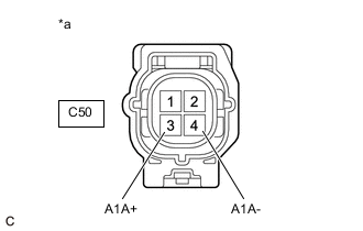
*a Front view of wire harness connector
(to Air Fuel Ratio Sensor (Sensor 1))
Tech Tips
Make sure that the connector is properly connected. If it is not, securely connect it and check for DTCs again.
-
Disconnect the air fuel ratio sensor (sensor 1) connector.
-
Turn the ignition switch to ON.
-
Measure the voltage according to the value(s) in the table below.
Standard Voltage Tester Connection Condition Specified Condition C50-3 (A1A+) - Body ground Ignition switch ON 2.8 to 3.0 V C50-4 (A1A-) - Body ground Ignition switch ON 2.3 to 2.7 V C50-3 (A1A+) - C50-4 (A1A-) Ignition switch ON 0.1 to 0.7 V Tech Tips
Perform "Inspection After Repair" after replacing the air fuel ratio sensor (sensor 1).
Result Proceed to OK NG
OK 
REPLACE AIR FUEL RATIO SENSOR (SENSOR 1) Click here
NG 
-
-
CHECK HARNESS AND CONNECTOR (AIR FUEL RATIO SENSOR (SENSOR 1) - ECM)
-
Disconnect the air fuel ratio sensor (sensor 1) connector.
-
Disconnect the ECM connector.
-
Measure the resistance according to the value(s) in the table below.
Standard Resistance Tester Connection Condition Specified Condition C50-1 (HA1A) - C57-9 (HA1A) Always Below 1 Ω C50-3 (A1A+) - C57-95 (A1A+) Always Below 1 Ω C50-4 (A1A-) - C57-94 (A1A-) Always Below 1 Ω C50-1 (HA1A) or C57-9 (HA1A) - Body ground and other terminals Always 10 kΩ or higher C50-3 (A1A+) or C57-95 (A1A+) - Body ground and other terminals Always 10 kΩ or higher C50-4 (A1A-) or C57-94 (A1A-) - Body ground and other terminals Always 10 kΩ or higher Result Proceed to OK NG
OK
REPLACE ECM Click here
NG
REPAIR OR REPLACE HARNESS OR CONNECTOR
-