SFI SYSTEM(w/ Canister Pump Module), Diagnostic DTC:P12D013, P12D113, P12D213, P12D313
| DTC Code | DTC Name |
|---|---|
| P12D013 | Fuel Pump Control (All Phase) Circuit Open |
| P12D113 | Fuel Pump Control (U Phase) Circuit Open |
| P12D213 | Fuel Pump Control (V Phase) Circuit Open |
| P12D313 | Fuel Pump Control (W Phase) Circuit Open |
DESCRIPTION
Refer to DTC P062712.
| DTC No. | Detection Item | DTC Detection Condition | Trouble Area | MIL | Memory | Note |
|---|---|---|---|---|---|---|
| P12D013 | Fuel Pump Control (All Phase) Circuit Open | When the fuel pump control ECU operation duty ratio is 3 to 65%, an open is detected in the FPU, FPV and FPW circuit for 3 seconds or more (2 trip detection logic). |
|
Comes on | DTC stored | SAE Code: P12D0 |
| P12D113 | Fuel Pump Control (U Phase) Circuit Open | When the fuel pump control ECU operation duty ratio is 3 to 65%, an open is detected in the FPU circuit for 3 seconds or more (2 trip detection logic). |
|
Comes on | DTC stored | SAE Code: P12D1 |
| P12D213 | Fuel Pump Control (V Phase) Circuit Open | When the fuel pump control ECU operation duty ratio is 3 to 65%, an open is detected in the FPV circuit for 3 seconds or more (2 trip detection logic). |
|
Comes on | DTC stored | SAE Code: P12D2 |
| P12D313 | Fuel Pump Control (W Phase) Circuit Open | When the fuel pump control ECU operation duty ratio is 3 to 65%, an open is detected in the FPW circuit for 3 seconds or more (2 trip detection logic). |
|
Comes on | DTC stored | SAE Code: P12D3 |
| DTC No. | Data List |
|---|---|
| P12D013 P12D113 P12D213 P12D313 |
Fuel Pump Control Duty Ratio |
MONITOR DESCRIPTION
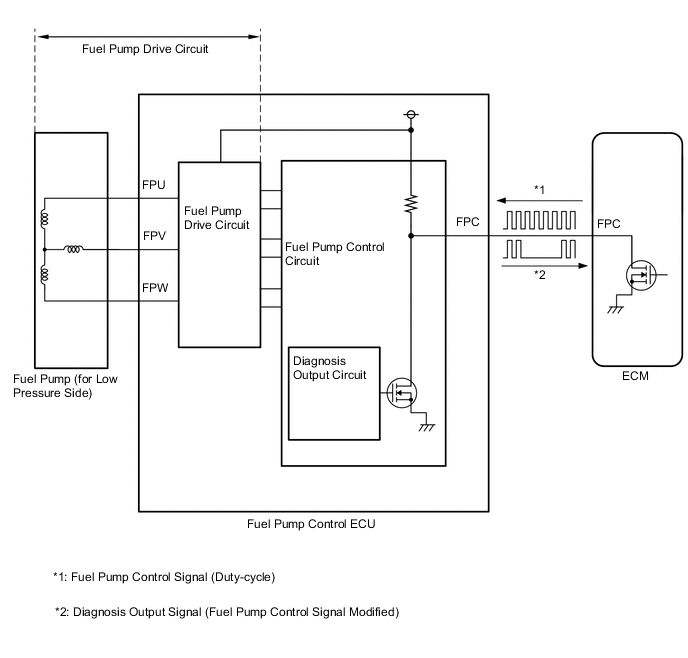
The fuel pump control ECU monitors the fuel pump drive circuit.
When a malfunction is detected in the fuel pump drive circuit, the diagnosis output circuit in the fuel pump control ECU modifies the operation signal sent by the ECM to indicate that there is a malfunction.
When the fuel pump control ECU operation duty ratio is 3 to 65% and the FPU, FPV or FPW terminal voltage is less than a certain value for 3 seconds or more, the diagnosis output circuit in the fuel pump control ECU modifies the operation signal sent by the ECM to indicate that there is a malfunction, and the ECM stores a DTC.
MONITOR STRATEGY
| Required Sensors/Components | Fuel pump control ECU |
| Frequency of Operation | Continuous |
CONFIRMATION DRIVING PATTERN
-
Connect the GTS to the DLC3.
-
Turn the engine switch on (IG).
-
Turn the GTS on.
-
Clear the DTCs (even if no DTCs are stored, perform the clear DTC procedure).
-
Turn the engine switch off and wait for at least 30 seconds.
-
Start the engine.
-
Wait 10 seconds or more.
-
Turn the GTS on.
-
Enter the following menus: Powertrain / Engine / Trouble Codes.
-
Read the pending DTCs.
Tech Tips
-
If a pending DTC is output, the system is malfunctioning.
-
If a pending DTC is not output, perform the following procedure.
-
-
Enter the following menus: Powertrain / Engine / Utility / All Readiness.
-
Input the DTC: P12D013, P12D113, P12D213 or P12D313.
-
Check the DTC judgment result.
GTS Display Description NORMAL
-
DTC judgment completed
-
System normal
ABNORMAL
-
DTC judgment completed
-
System abnormal
INCOMPLETE
-
DTC judgment not completed
-
Perform driving pattern after confirming DTC enabling conditions
Tech Tips
-
If the judgment result is NORMAL, the system is normal.
-
If the judgment result is ABNORMAL, the system is malfunctioning.
-
If the judgment result is INCOMPLETE, run the engine at an engine speed of 2000 rpm or more for 10 seconds or more and check the DTC judgment result again.
-
CAUTION / NOTICE / HINT
Tech Tips
Read Freeze Frame Data using the GTS. The ECM records vehicle and driving condition information as Freeze Frame Data the moment a DTC is stored. When troubleshooting, Freeze Frame Data can help determine if the vehicle was moving or stationary, if the engine was warmed up or not, if the air fuel ratio was lean or rich, and other data from the time the malfunction occurred.
PROCEDURE
-
PERFORM ACTIVE TEST USING GTS (FUEL PUMP SINGLE PHASE ENERGIZATION)
*1 Fuel Pump Control ECU - - Tech Tips
Make sure that the connector is properly connected. If it is not, securely connect it and check for DTCs again.
-
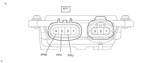
Disconnect the R17 fuel pump control ECU connector.
-
Connect the GTS to the DLC3.
-
Turn the engine switch on (IG).
-
Turn the GTS on.
-
Enter the following menus: Powertrain / Engine / Active Test / Fuel Pump Single Phase Energization.
Powertrain > Engine > Active TestTester Display Fuel Pump Single Phase Energization -
Operate the fuel pump control ECU using the Active Test function and measure the voltage according to the value(s) in the table below.
Standard Voltage Tester Connection GTS Operation Specified Condition R17-2 (FPU) - Body ground U Phase 4.4 to 8.4 V* R17-3 (FPV) - Body ground V Phase 4.4 to 8.4 V* R17-4 (FPW) - Body ground W Phase 4.4 to 8.4 V* Tech Tips
-
*: This Active Test limits the fuel pump control ECU output duty cycle to 50%. Therefore, the output voltage of the fuel pump control ECU will be approximately 50% of the power source voltage (+B terminal).
-
Before performing this inspection, check that the battery voltage is between 11 and 14 V (not depleted).
Result Proceed to OK NG -
NG 
REPLACE FUEL PUMP CONTROL ECU Click here
OK 
-
-
CHECK HARNESS AND CONNECTOR (FUEL PUMP CONTROL ECU - FUEL PUMP (FOR LOW PRESSURE SIDE))
Tech Tips
Make sure that the connector is properly connected. If it is not, securely connect it and check for DTCs again.
-
Disconnect the fuel pump control ECU connector.
-
Disconnect the fuel pump (for low pressure side) connector.
-
Measure the resistance according to the value(s) in the table below.
Standard Resistance Tester Connection Condition Specified Condition R17-2 (FPU) - R43-3 (BLPU) Always Below 1 Ω R17-3 (FPV) - R43-4 (BLPV) Always Below 1 Ω R17-4 (FPW) - R43-2 (BLPW) Always Below 1 Ω Result Proceed to OK NG Tech Tips
Perform "Inspection After Repair" after replacing the fuel pump (for low pressure side).
OK
REPLACE FUEL PUMP (FOR LOW PRESSURE SIDE) Click here
NG
REPAIR OR REPLACE HARNESS OR CONNECTOR
-