SFI SYSTEM, Diagnostic DTC:P0335, P0339
| DTC Code | DTC Name |
|---|---|
| P0335 | Crankshaft Position Sensor "A" Circuit |
| P0339 | Crankshaft Position Sensor "A" Circuit Intermittent |
DESCRIPTION
The crankshaft position sensor system consists of a crank angle sensor plate and a pickup coil.
The crank angle sensor plate has 34 teeth and is installed on the crankshaft. The pickup coil is made of wound copper wire, an iron core and a magnet. The crank angle sensor plate rotates and, as each tooth passes by the pickup coil, a pulse signal is created. The pickup coil generates 34 signals per engine speed. Based on these signals, the ECM calculates the crankshaft position and engine speed. Using these calculations, the fuel injection duration and ignition timing are controlled.
| DTC No. | Detection Item | DTC Detection Condition | Trouble Area | MIL | Memory |
|---|---|---|---|---|---|
| P0335 | Crankshaft Position Sensor "A" Circuit | One of the following conditions is met (1 trip detection logic):
|
|
Comes on | DTC stored |
| P0339 | Crankshaft Position Sensor "A" Circuit Intermittent | Under conditions (a), (b) and (c), no crankshaft position sensor signal to ECM for 0.05 seconds or more (1 trip detection logic): (a) Engine speed is 1000 rpm or higher. (b) Starter signal off. (c) 3 seconds or more have elapsed since starter signal switched from on to off. |
|
Does not come on | DTC stored |
-
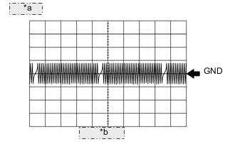
*a 5 V/DIV. *b 20 ms./DIV. Reference: Inspection using an oscilloscope.
Tech Tips
-
The correct waveform is as shown.
-
Grounding failure of the shielded wire may cause a noisy waveform.
ECM Terminal Name Between NE+ and NE- Tester Range 5 V/DIV., 20 ms./DIV. Condition Idling with warm engine -
MONITOR DESCRIPTION
If there is no signal from the crankshaft position sensor despite the crankshaft rotating, the ECM interprets this as a malfunction of the sensor.
MONITOR STRATEGY
| Required Sensors/Components (Main) | Crankshaft position sensor |
| Required Sensors/Components (Related) | Camshaft position sensor |
| Frequency of Operation | Continuous |
CONFIRMATION DRIVING PATTERN
-
Connect the GTS to the DLC3.
-
Turn the ignition switch to ON.
-
Turn the GTS on.
-
Clear the DTCs (even if no DTCs are stored, perform the clear DTC procedure).
-
Turn the ignition switch off and wait for at least 30 seconds.
-
Turn the ignition switch to ON.
-
Turn the GTS on.
-
Start the engine.
-
Idle the engine for 20 seconds or more [A].
-
Enter the following menus: Powertrain / Engine and ECT / Trouble Codes [B].
-
Read the pending DTCs.
Tech Tips
-
If a pending DTC is output, the system is malfunctioning.
-
If a pending DTC is not output, perform the following procedure.
-
-
Enter the following menus: Powertrain / Engine and ECT / Utility / All Readiness.
-
Input the DTC: P0335 or P0339.
-
Check the DTC judgment result.
GTS Display Description NORMAL
-
DTC judgment completed
-
System normal
ABNORMAL
-
DTC judgment completed
-
System abnormal
INCOMPLETE
-
DTC judgment not completed
-
Perform driving pattern after confirming DTC enabling conditions
N/A
-
Unable to perform DTC judgment
-
Number of DTCs which do not fulfill DTC preconditions has reached ECU memory limit
Tech Tips
-
If the judgment result shows NORMAL, the system is normal.
-
If the judgment result shows ABNORMAL, the system has a malfunction.
-
If the judgment result shows INCOMPLETE or N/A, perform steps [A] and [B] again.
-
WIRING DIAGRAM
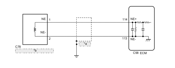
| *a | Shielded |
| *b | Crankshaft Position Sensor |
CAUTION / NOTICE / HINT
Tech Tips
-
After performing the inspection procedure for the crankshaft position sensor, if DTC P0335 is output again, check the following items related to the camshaft position sensor.
-
Installation condition of the camshaft position sensor
-
Installation condition of the camshaft
-
Connection of the camshaft position sensor connector
-
If no problem is found by this diagnostic troubleshooting procedure, check for problems by referring to the engine mechanical section.
-
The engine speed can be checked by using the GTS. To perform the check, follow the procedures below:
-
Connect the GTS to the DLC3.
-
Start the engine.
-
Turn the GTS on.
-
Enter the following menus: Powertrain / Engine and ECT / Data List / Primary / Engine Speed.
-
The engine speed may be indicated as zero despite the engine running normally. This is caused by a lack of NE signals from the crankshaft position sensor. Alternatively, the engine speed may be indicated as lower than the actual engine speed if the crankshaft position sensor output voltage is insufficient.
-
Read Freeze Frame Data using the GTS. The ECM records vehicle and driving condition information as Freeze Frame Data the moment a DTC is stored. When troubleshooting, Freeze Frame Data can help determine if the vehicle was moving or stationary, if the engine was warmed up or not, if the air fuel ratio was lean or rich, and other data from the time the malfunction occurred.
PROCEDURE
-
READ VALUE USING GTS (ENGINE SPEED)
-
Connect the GTS to the DLC3.
-
Turn the ignition switch to ON.
-
Turn the GTS on.
-
Enter the following menus: Powertrain / Engine and ECT / Data List / Engine Speed.
Powertrain > Engine and ECT > Data ListTester Display Engine Speed -
Start the engine.
-
Read the values displayed on the GTS while the engine is running.
Standard Correct values are displayed. Tech Tips
-
To check the engine speed change, display the graph on the GTS.
-
If the engine does not start, check the engine speed while cranking.
-
If the engine speed indicated on the GTS remains at zero (0), there may be an open or short in the crankshaft position sensor circuit.
Result Proceed to OK NG -
OK 
CHECK FOR INTERMITTENT PROBLEMS Click here
NG 
-
-
INSPECT CRANKSHAFT POSITION SENSOR (RESISTANCE)
-
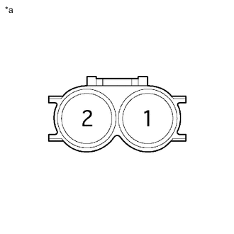
*a Component without harness connected
(Crankshaft Position Sensor)
Disconnect the crankshaft position sensor connector.
-
Measure the resistance according to the value(s) in the table below.
Standard Resistance Tester Connection Condition Specified Condition 1 - 2 Cold 1630 to 2740 Ω Hot 2065 to 3225 Ω Tech Tips
In the table above, the terms "Cold" and "Hot" mean the temperature of the coils themselves. "Cold" is from -10 to 50°C (14 to 122°F) and "Hot" is from 50 to 100°C (122 to 212°F).
Result Proceed to OK NG
NG
REPLACE CRANKSHAFT POSITION SENSOR Click here
OK
-
-
CHECK HARNESS AND CONNECTOR (CRANKSHAFT POSITION SENSOR - ECM)
-
Disconnect the crankshaft position sensor connector.
-
Disconnect the ECM connector.
-
Measure the resistance according to the value(s) in the table below.
Standard Resistance Tester Connection Condition Specified Condition C78-1 (NE) - C58-76 (NE+) Always Below 1 Ω C78-2 (NE-) - C58-109 (NE-) Always Below 1 Ω C78-1 (NE) or C58-76 (NE+) - Body ground Always 10 kΩ or higher C78-2 (NE-) or C58-109 (NE-) - Body ground Always 10 kΩ or higher Result Proceed to OK NG
NG
REPAIR OR REPLACE HARNESS OR CONNECTOR
OK
-
-
CHECK SENSOR INSTALLATION (CRANKSHAFT POSITION SENSOR)
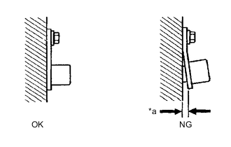
*a Clearance
-
Check the crankshaft position sensor installation condition.
OK Crankshaft position sensor is installed correctly. Result Proceed to OK NG
NG
SECURELY REINSTALL CRANKSHAFT POSITION SENSOR Click here
OK
-
-
INSPECT CRANKSHAFT (TEETH OF CRANK ANGLE SENSOR PLATE)
-
Inspect the teeth of the crank angle sensor plate.
OK Crank angle sensor plate does not have any cracks or deformation. Result Proceed to OK NG
OK
REPLACE ECM Click here
NG
REPLACE CRANKSHAFT Click here
-