BRAKE VACUUM HOSE(for LHD) INSTALLATION
PROCEDURE
-
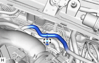
INSTALL NO. 1 HOSE TO HOSE TUBE (for 2AR-FE)
-
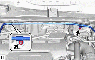
Install the No. 1 hose to hose tube with the 2 nuts.
- Torque:
- 5.4 N*m { 55 kgf*cm, 48 in.*lbf }
-
-
INSTALL UNION TO CONNECTOR TUBE HOSE (for 2AR-FE)
-
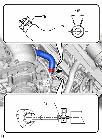
Install the 2 clips to the union to connector tube hose.
-
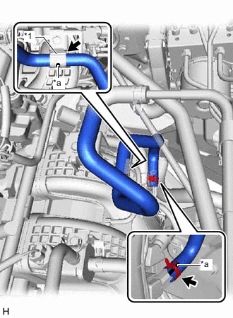
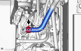
*1 Vacuum Hose Clamp *a Paint Mark Connect the union to connector tube hose to the intake manifold and slide the clip to secure it.
Note
-
When connecting the union to connector tube hose, face the paint mark up.
-
Make sure that the tabs of the clip are facing upward.
-
-
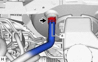
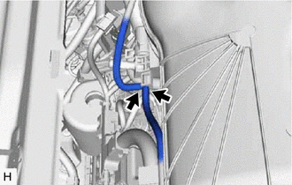
Install the union to connector tube hose to the vacuum hose clamp.
Note
When installing the union to connector tube hose to the vacuum hose clamp, make sure to align the paint mark with the vacuum hose clamp as shown in the illustration.
-
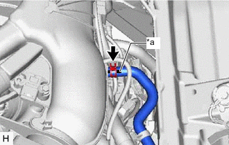
*a Paint Mark Connect the union to connector tube hose to the No. 1 hose to hose tube and slide the clip to secure it.
Note
-
When connecting the union to connector tube hose, face the paint mark up.
-
Make sure that the tabs of the clip are facing the left side of the vehicle.
-
-
-
INSTALL CHECK VALVE TO CONNECTOR TUBE HOSE (for 2AR-FE)
-
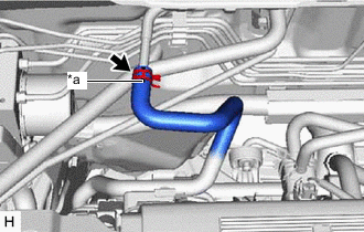
Install the 2 clips to the check valve to connector tube hose.
-
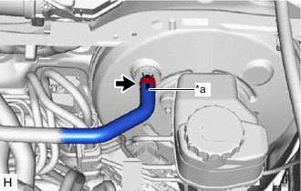
*a Paint Mark Connect the check valve to connector tube hose to the No. 1 hose to hose tube and slide the clip to secure it.
Note
-
When connecting the check valve to connector tube hose, face the paint mark up.
-
Make sure that the tabs of the clip are facing upward.
-
-
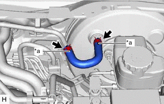
Connect the check valve to connector tube hose to the brake booster assembly and slide the clip to secure it.
Note
-
When connecting the check valve to connector tube hose, face the paint mark up.
-
Make sure that the tabs of the clip are facing upward.
-
-
-
INSTALL NO. 1 VACUUM HOSE CONNECTOR (for A25A-FKS)
-
Align the No. 1 vacuum hose connector with the vacuum pump assembly, and push them together until the No. 1 vacuum hose connector makes a "click" sound.
Note
-
Check that there is no foreign matter on the connecting parts.
-
After connecting the No. 1 vacuum hose connector, check that the vacuum pump assembly and No. 1 vacuum hose connector are securely connected by pulling on them.
-
-
Connect the vacuum hose to the No. 1 vacuum hose connector.
-
-
INSTALL UNION TO CHECK VALVE HOSE (for A25A-FKS)
-
Install the 2 clips to the union to check valve hose.
-
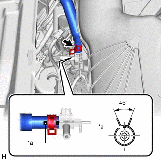
*a Paint Mark Connect the union to check valve hose to the No. 1 vacuum hose connector and slide the clip to secure it.
Note
-
When connecting the union to check valve hose, face the paint mark up.
-
Make sure that the tabs of the clip is facing the back of the vehicle.
-
-
*a Paint Mark Connect the union to check valve hose to the brake booster assembly and slide the clip to secure it.
Note
-
When connecting the union to check valve hose, face the paint mark up.
-
Make sure that the tabs of the clip are facing upward.
-
-
-
INSTALL AIR TUBE (for 2GR-FKS)
-
Engage the clamp to install the air delivery way to the intake air surge tank assembly.
-
Install the 2 clips to the air tube.
-
*a Paint Mark Connect the air tube to the air delivery way and slide the clip to secure it.
Note
-
Make sure to position the paint mark of the air tube as shown in the illustration.
-
Make sure that the tabs of the clip are aligned as shown in the illustration.
-
-
*a Paint Mark *b Dot Paint Connect the air tube to the vacuum pump assembly and slide the clip to secure it.
Note
-
Make sure to position the paint mark of the air tube as shown in the illustration.
-
Make sure that the tabs of the clip are aligned as shown in the illustration.
-
-
Connect the 2 vacuum transmitting hose assemblies to the air delivery way.
-
-
INSTALL UNION TO CHECK VALVE HOSE (for 2GR-FKS)
-
Install the 2 clips to the union to check valve hose.
-
*a Paint Mark Connect the union to check valve hose to the air delivery way and slide the clip to secure it.
Note
-
When connecting the union to check valve hose, face the paint mark up.
-
Make sure that the tabs of the clip are facing upward.
-
-
*a Paint Mark Connect the union to check valve hose to the brake booster assembly and slide the clip to secure it.
Note
-
When connecting the union to check valve hose, face the paint mark up.
-
Make sure that the tabs of the clip are facing upward.
-
-
Engage the clamp to install the union to check valve hose to the air tube.
-
-
INSTALL FRONT CENTER UPPER SUSPENSION BRACE SUB-ASSEMBLY (for 2AR-FE, 2GR-FKS)
-
INSTALL COWL TOP VENTILATOR LOUVER SUB-ASSEMBLY (for 2AR-FE, 2GR-FKS)