AIR CONDITIONING FILTER INSTALLATION
PROCEDURE
-
INSTALL CLEAN AIR FILTER
-
Engage the 2 guides on the cutout side of the air filter case and then engage the 2 guides as shown in the illustration to install the clean air filter.
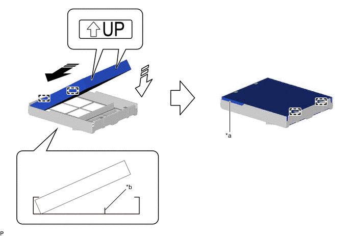
*a Cutout *b Rib 
Install in this Direction (1) 
Install in this Direction (2) Note
-
Make sure that the "UP" marks are facing the correct direction before installing the clean air filter.
-
Make sure that there is no clearance between the clean air filter and air filter case and that the clean air filter is not deformed.
-
-
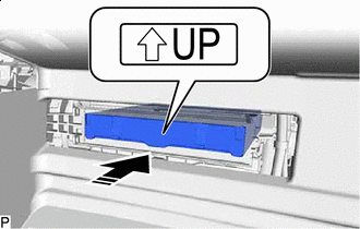
Install in this Direction Install the air filter sub-assembly as shown in the illustration.
Note
Make sure that the "UP" mark is facing the correct direction before installing the air filter sub-assembly.
-
-
INSTALL AIR FILTER COVER PLATE
-
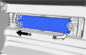
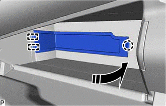
Install in this Direction (1) Install in this Direction (2) Engage the 2 guides and claw as indicated by the arrows, in the order shown in the illustration to install the air filter cover plate.
-
-
INSTALL GLOVE COMPARTMENT DOOR ASSEMBLY (for Type A)
-
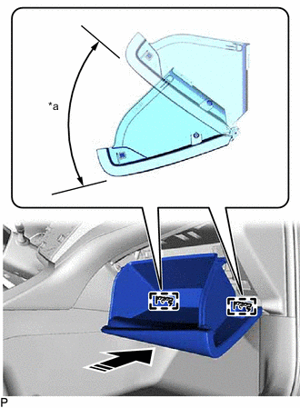
*a 60° Install in this Direction With the glove compartment door assembly opened approximately 60° from its closed position, engage the 2 hinges horizontally.
Note
Engaging the hinges from an upward angle will deform the hinges. Be sure to install the glove compartment door assembly horizontally.
-
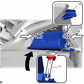
*1 Glove Compartment Door Stopper Sub-assembly *a Stopper Slightly bend the stoppers (A) and (B) in the directions indicated by the arrows shown in the illustration and engage the stoppers to install the glove compartment door assembly.
-
Engage the claw to connect the glove compartment door stopper sub-assembly.
-
-
INSTALL LOWER INSTRUMENT COVER LH (for Type B)
-
Install in this Direction Engage the 2 guides and claw to install the lower instrument cover LH as shown in the illustration.
-