AUTOMATIC TRANSAXLE SYSTEM Shift Paddle Switch Circuit
DESCRIPTION
Moving the shift lever to S enables the shift range to be selected. The shift range can be selected by operating the "+" or "-" shift paddle switch.
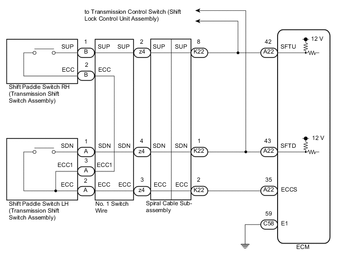
WIRING DIAGRAM
CAUTION / NOTICE / HINT
Note
After turning the ignition switch off, waiting time may be required before disconnecting the cable from the negative (-) battery terminal. Therefore, make sure to read the disconnecting the cable from the negative (-) battery terminal notices before proceeding with work.
PROCEDURE
-
READ VALUE USING GTS (SPORT SHIFT UP SW AND SPORTS SHIFT DOWN SW)
-
Connect the GTS to the DLC3.
-
Turn the ignition switch to ON.
-
Turn the GTS on.
-
Enter the following menus: Powertrain / Engine and ECT / Data List.
-
According to the display on the GTS, read the Data List.
Powertrain > Engine and ECT > Data ListTester Display Measurement Item Range Normal Condition Diagnostic Note Sports Shift Up SW Sport shift up switch status ON or OFF
-
ON: Shift lever held in "+" or "+" shift paddle switch operated
-
OFF: Shift lever not held in "+" and "+" shift paddle switch released
- Sports Shift Down SW Sport shift down switch status ON or OFF
-
ON: Shift lever held in "-" or "-" shift paddle switch operated
-
OFF: Shift lever not held in "-" and "-" shift paddle switch released
-
Powertrain > Engine and ECT > Data ListTester Display Sports Shift Up SW Sports Shift Down SW Result Result Proceed to Data List values are normal A Data List values are not normal B -
A 
CHECK FOR INTERMITTENT PROBLEMS Click here
B 
-
-
CHECK HARNESS AND CONNECTOR (SHIFT PADDLE SWITCH CIRCUIT)
-
Disconnect the A22 ECM connector.
-
Measure the resistance according to the value(s) in the table below.
Standard Resistance Tester Connection Condition Specified Condition A22-42 (SFTU) - A22-35 (ECCS) "+" (Up shift) shift paddle switch operated and held Below 13 Ω "+" (Up shift) shift paddle switch not operated 10 kΩ or higher A22-43 (SFTD) - A22-35 (ECCS) "-" (Down shift) shift paddle switch operated and held Below 13 Ω "-" (Down shift) shift paddle switch not operated 10 kΩ or higher Result Proceed to OK NG
NG 
CHECK HARNESS AND CONNECTOR (SPIRAL CABLE SUB-ASSEMBLY - ECM) Click here
OK
-
-
CHECK HARNESS AND CONNECTOR (ECM - BODY GROUND)
-
Disconnect the C58 ECM connector.
-
Measure the resistance according to the value(s) in the table below.
Standard Resistance Tester Connection Condition Specified Condition C58-59 (E1) - Body ground Always Below 1 Ω Result Proceed to OK NG
OK
PROCEED TO NEXT SUSPECTED AREA SHOWN IN PROBLEM SYMPTOMS TABLE Click here
NG
REPAIR OR REPLACE HARNESS OR CONNECTOR (ECM - BODY GROUND)
-
-
CHECK HARNESS AND CONNECTOR (SPIRAL CABLE SUB-ASSEMBLY - ECM)
-
Disconnect the A22 ECM connector.
-
Disconnect the K22 spiral cable sub-assembly connector.
-
Measure the resistance according to the value(s) in the table below.
Standard Resistance Tester Connection Condition Specified Condition A22-42 (SFTU) - K22-8 (SUP) Always Below 1 Ω A22-43 (SFTD) - K22-1 (SDN) Always Below 1 Ω A22-35 (ECCS) - K22-2 (ECC) Always Below 1 Ω A22-42 (SFTU) or K22-8 (SUP) - Body ground Always 10 kΩ or higher A22-43 (SFTD) or K22-1 (SDN) - Body ground Always 10 kΩ or higher A22-35 (ECCS) or K22-2 (ECC) - Body ground Always 10 kΩ or higher Result Proceed to OK NG
NG
REPAIR OR REPLACE HARNESS OR CONNECTOR (SPIRAL CABLE SUB-ASSEMBLY - ECM)
OK
-
-
INSPECT SPIRAL CABLE SUB-ASSEMBLY
-
Inspect the spiral cable sub-assembly.
Result Proceed to OK NG
NG
REPLACE SPIRAL CABLE SUB-ASSEMBLY Click here
OK
-
-
INSPECT SHIFT PADDLE SWITCH LH (TRANSMISSION SHIFT SWITCH ASSEMBLY)
-
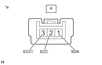
*a Component without harness connected
(Shift Paddle Switch LH (Transmission Shift Switch Assembly))
Remove the shift paddle switch LH (transmission shift switch assembly).
-
Measure the resistance according to the value(s) in the table below.
Standard Resistance Tester Connection Condition Specified Condition A-1 (SDN) - A-2 (ECC) "-" (Down shift) shift paddle switch operated and held Below 13 Ω "-" (Down shift) shift paddle switch not operated 10 kΩ or higher A-1 (SDN) - A-3 (ECC1) "-" (Down shift) shift paddle switch operated and held Below 13 Ω "-" (Down shift) shift paddle switch not operated 10 kΩ or higher Result Proceed to OK NG
NG
REPLACE SHIFT PADDLE SWITCH LH (TRANSMISSION SHIFT SWITCH ASSEMBLY) Click here
OK
-
-
INSPECT SHIFT PADDLE SWITCH RH (TRANSMISSION SHIFT SWITCH ASSEMBLY)
-
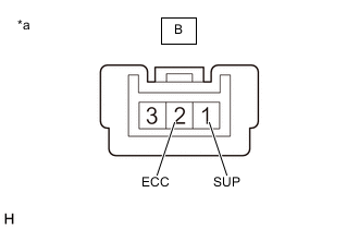
*a Component without harness connected
(Shift Paddle Switch RH (Transmission Shift Switch Assembly))
Remove the shift paddle switch RH (transmission shift switch assembly).
-
Measure the resistance according to the value(s) in the table below.
Standard Resistance Tester Connection Condition Specified Condition B-1 (SUP) - B-2 (ECC) "+" (Up shift) shift paddle switch operated and held Below 13 Ω "+" (Up shift) shift paddle switch not operated 10 kΩ or higher Result Proceed to OK NG
NG
REPLACE SHIFT PADDLE SWITCH RH (TRANSMISSION SHIFT SWITCH ASSEMBLY) Click here
OK
-
-
INSPECT NO. 1 SWITCH WIRE
-
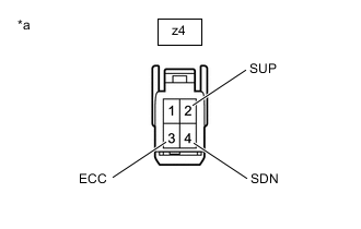
*a Front view of wire harness connector
(to Spiral Cable Sub-assembly)
Install the transmission shift switch assembly.
-
Disconnect the z4 No. 1 switch wire connector.
-
Measure the resistance according to the value(s) in the table below.
Standard Resistance Tester Connection Condition Specified Condition z4-2 (SUP) - z4-3 (ECC) "+" (Up shift) shift paddle switch operated and held Below 13 Ω "+" (Up shift) shift paddle switch not operated 10 kΩ or higher z4-4 (SDN) - z4-3 (ECC) "-" (Down shift) shift paddle switch operated and held Below 13 Ω "-" (Down shift) shift paddle switch not operated 10 kΩ or higher Result Proceed to OK NG
OK
PROCEED TO NEXT SUSPECTED AREA SHOWN IN PROBLEM SYMPTOMS TABLE Click here
NG
REPLACE NO. 1 SWITCH WIRE Click here
-