AUTOMATIC TRANSAXLE UNIT INSPECTION

PROCEDURE
-
INSPECT TRANSMISSION OIL CLEANER MAGNET
-
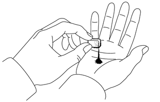
Use the removed transmission oil cleaner magnets to collect any steel chips. Examine the chips and particles in the transaxle housing and on the transmission oil cleaner magnets to determine what type of wear might be found in the automatic transaxle assembly.
Result Steel (magnetic) Bearing, gear and plate wear Brass (non-magnetic) Bushing wear
-
-
INSPECT FRONT CLUTCH CLUTCH DISC
-
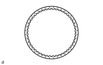
Check if the contact surfaces of the front clutch clutch disc, forward multiple disc clutch clutch plate and forward clutch flange are worn or burnt.
If necessary, replace them.
Note
-
If the lining of any front clutch clutch disc is peeled off or discolored, or even if part of the groove is damaged, replace all the front clutch clutch disc.
-
Before assembling new front clutch clutch disc, soak them in Toyota Genuine ATF WS for at least 15 minutes.
-
-
-
INSPECT NO. 2 CLUTCH DISC
-
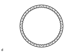
Check if the contact surfaces of the No. 2 clutch disc, No. 2 clutch plate and direct clutch flange are worn or burnt.
If necessary, replace them.
Note
-
If the lining of any No. 2 clutch disc is peeled off or discolored, or even if part of the groove is damaged, replace all the No. 2 clutch disc.
-
Before assembling new No. 2 clutch disc soak them in Toyota Genuine ATF WS for at least 15 minutes.
-
-
-
INSPECT NO. 1 BRAKE DISC
-
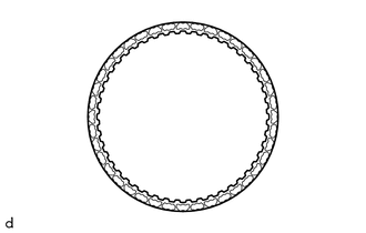
Check if the contact surfaces of the No. 1 brake disc, No. 1 brake plate and No. 1 brake flange are worn or burnt.
If necessary, replace them.
Note
-
If the lining of any No. 1 brake disc is peeled off or discolored, or even if part of the groove is damaged, replace all the No. 1 brake disc.
-
Before assembling new No. 1 brake disc, soak them in Toyota Genuine ATF WS for at least 15 minutes.
-
-
-
INSPECT 2ND BRAKE BRAKE DISC
-
Check if the contact surfaces of the 2nd brake brake disc, 2nd brake brake plate and 2nd brake brake flange are worn or burnt.
If necessary, replace them.
Note
-
If the lining of any 2nd brake brake disc is peeled off or discolored, or even if part of the groove is damaged, replace all the 2nd brake brake disc.
-
Before assembling new 2nd brake brake disc, soak them in Toyota Genuine ATF WS for at least 15 minutes.
-
-
-
INSPECT CLUTCH RETURN SPRING SUB-ASSEMBLY
-
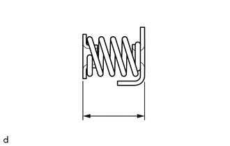
Using a vernier caliper, measure the free length of the clutch return spring sub-assembly together with the spring seat.
Standard Free Length 14.61 mm (0.575 in.) If the free length is shorter than the standard free length, replace the clutch return spring sub-assembly.
-
-
INSPECT 1ST AND REVERSE BRAKE RETURN SPRING SUB-ASSEMBLY
-
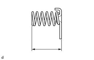
Using a vernier caliper, measure the free length of the 1st and reverse brake return spring sub-assembly together with the spring seat.
Standard Free Length 18.29 mm (0.720 in.) If the free length is shorter than the standard free length, replace the 1st and reverse brake return spring sub-assembly.
-
-
INSPECT PLANETARY SUN GEAR SUB-ASSEMBLY
-
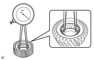
Using a caliper gauge, measure the inside diameter of the bushing of the planetary sun gear sub-assembly.
Standard Inside Diameter 33.286 to 33.312 mm (1.310 to 1.311 in.) Maximum Inside Diameter 33.312 mm (1.311 in.) If the inside diameter is more than the maximum, replace the planetary sun gear sub-assembly.
-
-
INSPECT REAR PLANETARY SUN GEAR SUB-ASSEMBLY
-
Using a caliper gauge, measure the inside diameter of the bushing of the rear planetary sun gear sub-assembly.
Standard Inside Diameter 24.287 to 24.313 mm (0.956 to 0.957 in.) Maximum Inside Diameter 24.313 mm (0.957 in.) If the inside diameter is more than the maximum, replace the rear planetary sun gear sub-assembly.
-
-
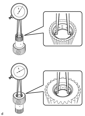
INSPECT FRONT PLANETARY GEAR ASSEMBLY
-
for Outer Pinion:
-
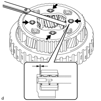
Using a feeler gauge, measure the clearance between the planetary carrier and pinion gears at 5 points.
Standard Clearance 0.2 to 0.6 mm (0.00787 to 0.0236 in.) If the clearance is more than the standard clearance, replace the front planetary gear assembly.
-
-
for Inner Pinion:
-
Using a feeler gauge, measure the clearance between the planetary carrier and pinion gears at 5 points.
Standard Clearance 0.2 to 0.6 mm (0.00787 to 0.0236 in.) If the clearance is more than the standard clearance, replace the front planetary gear assembly.
-
-
-
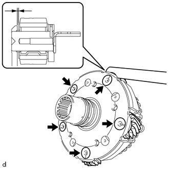
INSPECT REAR PLANETARY GEAR ASSEMBLY
-
for Long Pinion:
-
Using a feeler gauge, measure the clearance between the planetary carrier and pinion gears at 4 points.
Standard Clearance 0.15 to 1.05 mm (0.00591 to 0.0413 in.) If the clearance is more than the standard clearance, replace the rear planetary gear assembly.
-
-
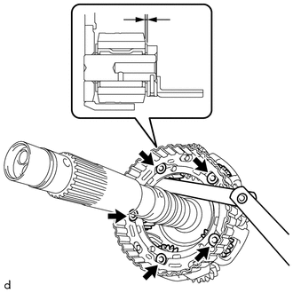
for Short Pinion:
-
Using a feeler gauge, measure the clearance between the planetary carrier and pinion gears at 4 points.
Standard Clearance 0.15 to 0.85 mm (0.00591 to 0.0335 in.) If the clearance is more than the standard clearance, replace the rear planetary gear assembly.
-
-
-
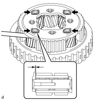
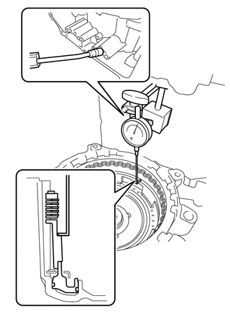
INSPECT INPUT SHAFT END PLAY
-
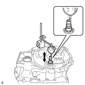
Using a dial indicator, measure the input shaft end play.
Standard Input Shaft End Play 0.332 to 1.103 mm (0.0131 to 0.0434 in.)
-
-
INSPECT CLEARANCE OF C-3 CLUTCH
-
Set the C-3 and C-4 clutch assembly on the front oil pump assembly.
-
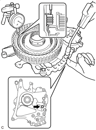

Cover Oil Hole Using a dial indicator, measure the clearance of the C-3 clutch while applying compressed air (approximately 200 kPa (2.0 kgf/cm2, 29 psi)).
Pack Clearance (Reference) 0.19 to 0.61 mm (0.00748 to 0.0240 in.) Tech Tips
-
Cover the location shown in the illustration with your finger when applying compressed air.
-
To find the clearance, measure in at least 3 locations and average the results.
If the clearance is not as specified, replace the C-3 and C-4 clutch assembly.
-
-
-
INSPECT CLEARANCE OF C-4 CLUTCH
-
Set the C-3 and C-4 clutch assembly on the front oil pump assembly.
-
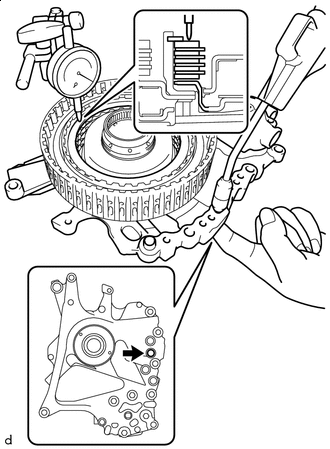
Cover Oil Hole Using a dial indicator, measure the clearance of the C-4 clutch while applying compressed air (approximately 400 kPa (4.1 kgf/cm2, 58 psi)).
Pack Clearance (Reference) 0.27 to 0.73 mm (0.0106 to 0.0287 in.) Tech Tips
-
Cover the location shown in the illustration with your finger when applying compressed air.
-
To find the clearance, measure in at least 3 locations and average the results.
If the clearance is not as specified, replace the C-3 and C-4 clutch assembly.
-
-
-
INSPECT CLEARANCE OF C-1 CLUTCH
-
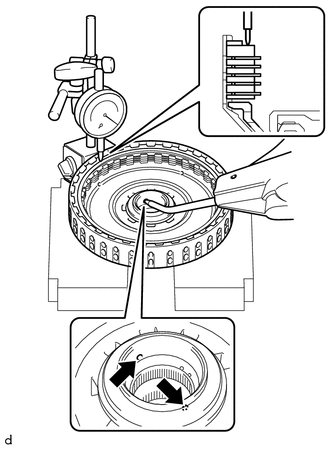
Using a dial indicator, measure the clearance of the C-1 clutch while applying compressed air (approximately 200 kPa (2.0 kgf/cm2, 29 psi)).
Pack Clearance (Reference) 1.0 to 1.2 mm (0.0394 to 0.0472 in.) Tech Tips
-
Make sure to cover the ATF holes shown in the illustration.
-
To find the clearance, measure in at least 3 locations and average the results.
If the clearance is not as specified, select an appropriate forward clutch flange so that the clearance will be within the specified range.
Forward Clutch Flange Thickness Part Number Thickness
mm (in.)
35635-48120 4.3 (0.169) 35635-48130 4.4 (0.173) 35635-48140 4.5 (0.177) 35635-48150 4.6 (0.181) 35635-48160 4.7 (0.185) 35635-48170 4.8 (0.189) 35635-48180 4.9 (0.193) 35635-48190 5.0 (0.197) 35635-48200 5.1 (0.201) -
-
-
INSPECT CLEARANCE OF B-1 BRAKE
Tech Tips
TMC (TOYOTA) Made and AW (AISIN AW) Made components can be identified by the differing locations where the serial number is stamped.
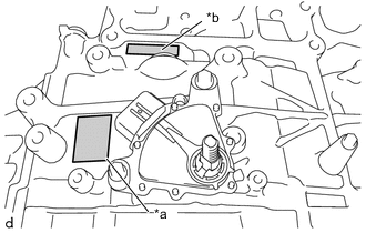
*a TMC Made *b AW Made
-
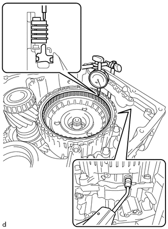
Using a dial indicator, measure the clearance of the B-1 brake while applying compressed air (approximately 200 kPa (2.0 kgf/cm2, 29 psi)).
Pack Clearance 0.8 to 1.0 mm (0.0315 to 0.0394 in.) Tech Tips
To find the clearance, measure in at least 3 locations and average the results.
If the clearance is not as specified, select an appropriate No. 1 brake flange so that the clearance will be within the specified range.
No. 1 Brake Flange Thickness for TMC Made: Part Number Thickness
mm (in.)
Mark 35676-48450 3.5 (0.138) 0 35676-48460 3.6 (0.142) 1 35676-48470 3.7 (0.146) 2 35676-48480 3.8 (0.150) 3 35676-48490 3.9 (0.154) 4 35676-48500 4.0 (0.157) 5 35676-48510 4.1 (0.161) 6 for AW Made: Part Number Thickness
mm (in.)
Mark 35676-48380 3.5 (0.138) 0 35676-48390 3.6 (0.142) 1 35676-48400 3.7 (0.146) 2 35676-48410 3.8 (0.150) 3 35676-48420 3.9 (0.154) 4 35676-48430 4.0 (0.157) 5 35676-48440 4.1 (0.161) 6
-
-
INSPECT CLEARANCE OF C-2 CLUTCH
Tech Tips
TMC (TOYOTA) Made and AW (AISIN AW) Made components can be identified by the differing locations where the serial number is stamped.
*a TMC Made *b AW Made
-
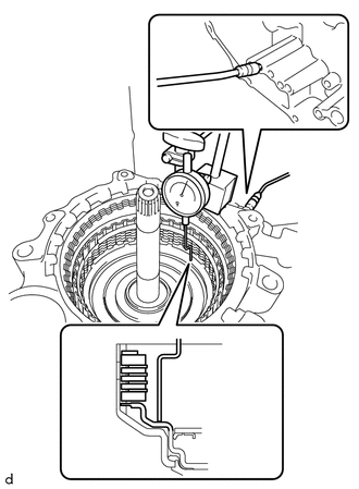
Using a dial indicator, measure the clearance of the C-2 clutch while applying compressed air (approximately 400 kPa (4.1 kgf/cm2, 58 psi)).
Piston Stroke 0.8 to 1.0 mm (0.0315 to 0.0394 in.) Tech Tips
To find the clearance, measure in at least 3 locations and average the results.
If the clearance is not as specified, select an appropriate direct clutch flange so that the clearance will be within the specified range.
Direct Clutch Flange Thickness for TMC Made: Part Number Thickness
mm (in.)
Mark 35675-48210 3.6 (0.142) 0 35675-48220 3.7 (0.146) 1 35675-48230 3.8 (0.150) 2 35675-48240 3.9 (0.154) 3 35675-48250 4.0 (0.157) 4 35675-48260 4.1 (0.161) 5 35675-48270 4.2 (0.165) 6 for AW Made: Part Number Thickness
mm (in.)
Mark 35675-48370 3.6 (0.142) 0 35675-48380 3.7 (0.146) 1 35675-48390 3.8 (0.150) 2 35675-48400 3.9 (0.154) 3 35675-48410 4.0 (0.157) 4 35675-48420 4.1 (0.161) 5 35675-48430 4.2 (0.165) 6
-
-
INSPECT CLEARANCE OF B-2 BRAKE
Tech Tips
TMC (TOYOTA) Made and AW (AISIN AW) Made components can be identified by the differing locations where the serial number is stamped.
*a TMC Made *b AW Made
-
Using a dial indicator, measure the clearance of the B-2 brake while applying compressed air (approximately 200 kPa (2.0 kgf/cm2, 29 psi)).
Piston Stroke 1.0 to 1.2 mm (0.0394 to 0.0472 in.) Tech Tips
To find the clearance, measure in at least 3 locations and average the results.
If the clearance is not as specified, select an appropriate 2nd brake brake flange so that the clearance will be within the specified range.
Tech Tips
There are 7 2nd brake brake flanges of different thicknesses available.
2nd Brake Brake Flange Thickness for TMC Made: Part Number Thickness
mm (in.)
Mark 35678-48110 5.0 (0.197) 0 35678-48120 5.1 (0.201) 1 35678-48130 5.2 (0.205) 2 35678-48140 5.3 (0.209) 3 35678-48150 5.4 (0.213) 4 35678-48160 5.5 (0.217) 5 35678-48170 5.6 (0.220) 6 for AW Made: Part Number Thickness
mm (in.)
Mark 35678-48040 5.0 (0.197) 0 35678-48050 5.1 (0.201) 1 35678-48060 5.2 (0.205) 2 35678-48070 5.3 (0.209) 3 35678-48080 5.4 (0.213) 4 35678-48090 5.5 (0.217) 5 35678-48100 5.6 (0.220) 6
-