AUTOMATIC TRANSAXLE ASSEMBLY REMOVAL
CAUTION / NOTICE / HINT
The necessary procedures (adjustment, calibration, initialization, or registration) that must be performed after parts are removed, installed, or replaced during automatic transaxle assembly removal/installation are shown below.
| Replaced Part or Performed Procedure | Necessary Procedure | Effect/Inoperative Function when Necessary Procedure not Performed | Link |
|---|---|---|---|
| Battery terminal is disconnected/reconnected | Perform steering sensor zero point calibration | Lane departure alert system (w/ Steering Control) | |
| Pre-collision system | |||
| Memorize steering angle neutral point | Parking assist monitor system | ||
| Replacement of ECM | Vehicle Identification Number (VIN) registration | MIL comes on | |
| Perform code registration (Immobiliser system) | Engine start function | See Service Bulletin for the registration method. | |
|
Inspection after repair |
|
|
| Replacement of automatic transaxle assembly |
|
|
for Initialization for Registration |
| Replacement of ECM (If possible, read the transaxle compensation code from the previous ECM) |
|
||
| Replacement of ECM (If impossible, read the transaxle compensation code from the previous ECM) |
|
||
| Replacement of ECM | Perform code registration (Immobiliser function) |
|
See Service Bulletin for the registration method. |
| Suspension, tires, etc. (The vehicle height changes because of suspension or tire replacement) |
Rear television camera assembly optical axis (Back camera position setting) | Parking assist monitor system | for Initialization for Calibration |
| Perform headlight ECU sub-assembly LH initialization | Lighting System (EXT) (w/ Automatic Headlight Beam Level Control System) | ||
| Front wheel alignment adjustment | Perform system variant learning and acceleration sensor zero point calibration. |
|
*1: When the ECM is replaced with a new one, reset memory is unnecessary.
CAUTION:
-
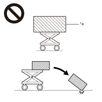
*a An Object Exceeding Weight Limit of Engine Lifter The engine assembly with transaxle is very heavy. Be sure to follow the procedure described in the repair manual, or the engine lifter may suddenly drop or the engine assembly with transaxle may fall off the engine lifter.
-
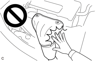
To prevent burns, do not touch the engine, exhaust manifold or other high temperature components while the engine is hot.
-
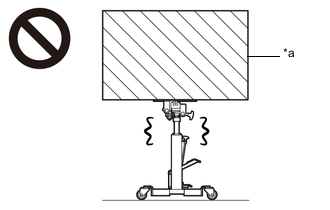
*a Object Exceeding Weight Limit of Transmission Jack The automatic transaxle assembly is very heavy. Be sure to follow the procedure described in the repair manual, or the transmission jack may suddenly drop.
PROCEDURE
-
REMOVE FLYWHEEL HOUSING UNDER COVER
-
REMOVE DRIVE PLATE AND TORQUE CONVERTER ASSEMBLY SETTING BOLT
-
Turn the crankshaft to gain access to the 6 drive plate and torque converter assembly setting bolts and remove each drive plate and torque converter assembly setting bolt while holding the crankshaft pulley bolt with a wrench.
Tech Tips
There will be one black colored drive plate and torque converter assembly setting bolt.
-
-
REMOVE ENGINE ASSEMBLY WITH TRANSAXLE
-
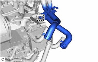
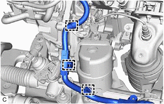
DISCONNECT VACUUM HOSE
-
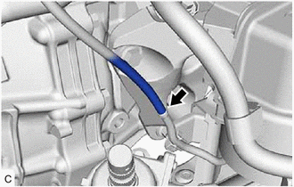
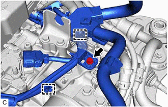
Disconnect the vacuum hose from the rear engine mounting insulator.
-
Disconnect the vacuum hose from the intake air surge tank assembly.
-
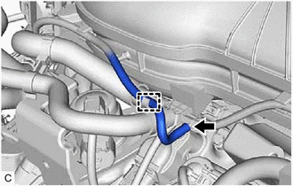
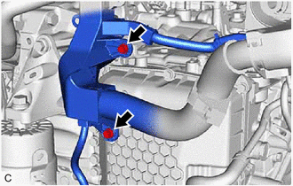
Disengage the clamp to disconnect the vacuum hose from the hose clamp.
-
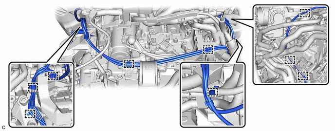
Disengage the 9 clamps to disconnect the vacuum hose from the automatic transaxle assembly.
-
-
REMOVE STARTER ASSEMBLY
-
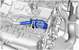
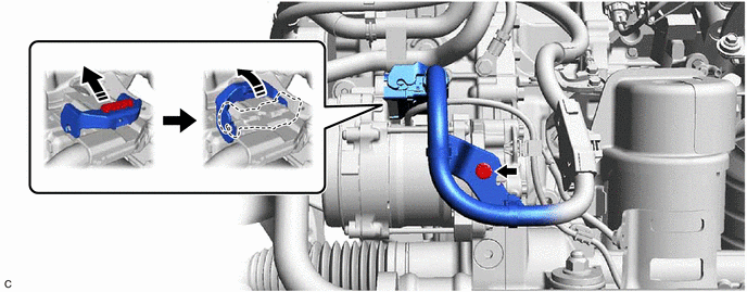
REMOVE BREATHER PLUG HOSE
-
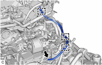
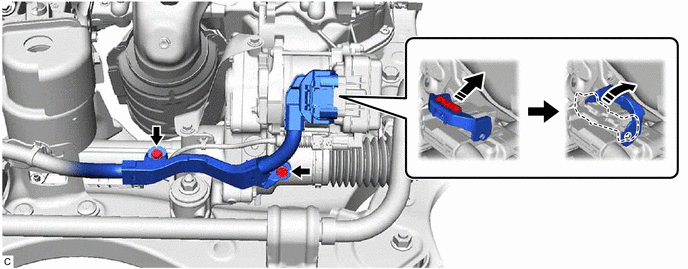
Disengage the 3 hose clamps to disconnect the breather plug hose.
-
Using a screwdriver with its tip wrapped with protective tape, remove the breather plug hose from the No. 1 breather plug (ATM).
Note
Be careful not to damage the No. 1 breather plug (ATM).
-
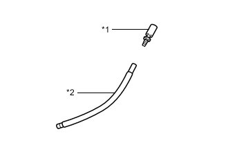
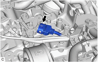
*1 Breather Plug Sub-assembly *2 Breather Plug Hose Remove the breather plug sub-assembly from the breather plug hose.
Note
Be careful not to damage the breather plug sub-assembly.
-
-
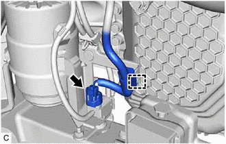
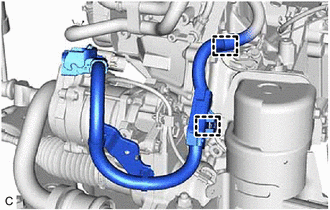
DISCONNECT NO. 1 WATER BY-PASS HOSE
-
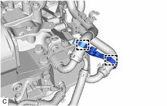
Disengage the 2 clamps to remove the transmission breather clamp.
-
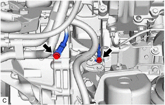
Slide the clip and disconnect the No. 1 water by-pass hose from the transmission oil cooler.
Tech Tips
Use a container to catch any coolant which flows out of the No. 1 water by-pass hose and transmission oil cooler.
-
-
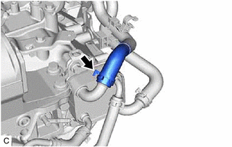
DISCONNECT WATER BY-PASS HOSE ASSEMBLY
-
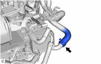
Slide the clip and disconnect the water by-pass hose assembly from the transmission oil cooler.
Tech Tips
Use a container to catch any coolant which flows out of the water by-pass hose assembly and transmission oil cooler.
-
Disengage the clamp to disconnect the water by-pass hose assembly from the automatic transaxle assembly.
-
-
DISCONNECT WIRE HARNESS
-
Disengage the claw, rotate the lever and disconnect the transmission wire connector.
-
Disconnect the park/neutral position switch assembly connector.
-
Disengage the wire harness clamp and disconnect the vacuum switching valve (for active control engine mount system) connector.
-
Remove the 2 bolts.
-
Remove the bolt.
-
Disengage the 2 wire harness clamps to disconnect the wire harness.
-
Remove the 2 bolts.
-
for LHD:
-
Disconnect the rack and pinion power steering gear assembly connector.
Tech Tips
Release the lock before rotating the lock lever.
-
Remove the 2 bolts to disconnect the wire harness.
-
Disengage the 3 wire harness clamps to disconnect the wire harness from the automatic transaxle assembly.
-
-
for RHD:
-
Disconnect the rack and pinion power steering gear assembly connector.
Tech Tips
Release the lock before rotating the lock lever.
-
Remove the bolt to disconnect the wire harness.
-
Disengage the 2 wire harness clamps to disconnect the wire harness.
-
-
-
INSTALL ENGINE HANGERS
-
REMOVE FRONT FRAME ASSEMBLY
-
REMOVE FRONT ENGINE MOUNTING BRACKET
-
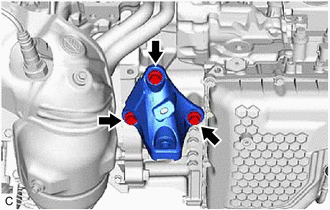
Remove the 3 bolts and front engine mounting bracket from the transaxle housing.
-
-
REMOVE AUTOMATIC TRANSAXLE ASSEMBLY
-
Support the automatic transaxle assembly with a transmission jack.
Note
Secure the automatic transaxle assembly to the transmission jack using a suitable adapter, such as a rope or attachment.
-
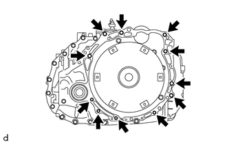
Remove the 11 bolts and automatic transaxle assembly.
Note
To prevent damage to the knock pins, do not pry between the automatic transaxle assembly and engine assembly.
-
-
REMOVE ENGINE MOUNTING INSULATOR LH
-
Remove the 5 bolts and engine mounting insulator LH from the automatic transaxle case sub-assembly.
-
-
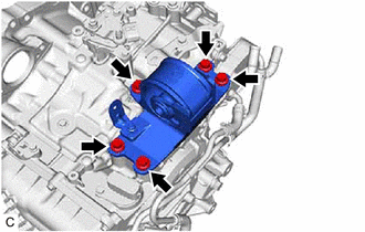
REMOVE REAR ENGINE MOUNTING INSULATOR
-
REMOVE REAR ENGINE MOUNTING BRACKET SUB-ASSEMBLY
-
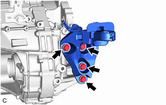
Remove the 4 bolts and rear engine mounting bracket sub-assembly from the transaxle housing.
-
-
DISCONNECT OUTLET NO. 1 OIL COOLER HOSE
-
DISCONNECT INLET NO. 1 OIL COOLER HOSE
-
REMOVE NO. 1 OIL COOLER TUBE SUB-ASSEMBLY WITHOUT HOSE
-
REMOVE TRANSMISSION OIL COOLER
-
REMOVE AUTOMATIC TRANSMISSION CASE COVER
-
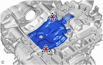
Remove the 2 clips and automatic transmission case cover from the automatic transaxle case sub-assembly.
-
-
REMOVE NO. 1 TRANSMISSION CONTROL CABLE BRACKET
-
Remove the 2 bolts and No. 1 transmission control cable bracket from the automatic transaxle case sub-assembly.
-
-
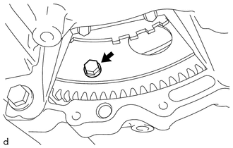
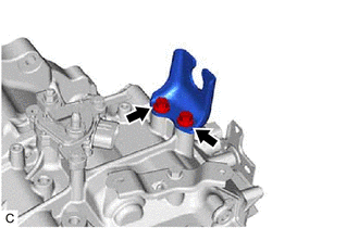
REMOVE TRANSMISSION CASE PLUG ASSEMBLY
-
Remove the transmission case plug assembly from the transaxle housing.
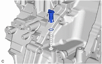
-
Remove the O-ring from the transmission case plug assembly.
-
-
REMOVE WIRE HARNESS CLAMP BRACKET
-
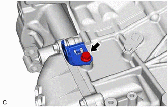
Remove the bolt and wire harness clamp bracket from the automatic transaxle case sub-assembly.
-
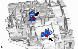
Remove the 2 bolts and 2 wire harness clamp brackets from the automatic transaxle case sub-assembly.
-
-
REMOVE TORQUE CONVERTER ASSEMBLY
-
Remove the torque converter assembly from the automatic transaxle assembly.
-
-
INSPECT TORQUE CONVERTER ASSEMBLY
-
INSPECT DRIVE PLATE AND RING GEAR SUB-ASSEMBLY